Solar Sailer II Upscale
In June 2013, I was nearing completion of my Comanche 3 and enjoyed it so much that I looked around for another classic Estes kit to upscale. After poring through the JimZ instruction archive, I settled on the Solar Sailer II (Estes #2044) which I fondly remembered building as a child.
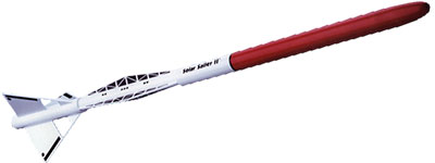
This kit is basically a normal rocket, but has an dual fin pattern with a cutout in the large fins. Like the Comanche, I decided to keep things simple by using 3.9" tubing for the main airframe, with 3.0" tubing for the reduced diameter middle section, giving me a 4.1x upscale.
The Pictures
The Design
This is a long section, starting with an overview of the design, so I've organized it into sub-sections:
First of all, the main drawing shows a simple upscale of the Estes kit. I used the JimZ instruction archive for reference.
Unlike the Comanche 3, this rocket has space for a long (33") 76mm motor mount tube so weight is not a critical issue. That means more straight-forward construction and plenty of space for electronics and recovery. So aside from the holes in the fins, this rocket is a pretty simple design.
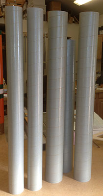
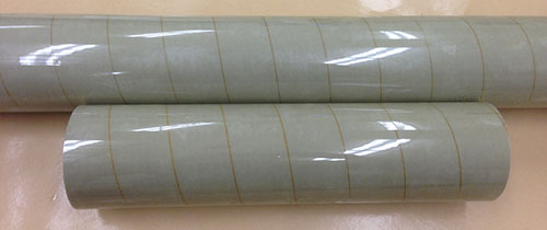
I had been curious about the vulcanized phenolic tubing (commonly known as "blue tube") that appeared a few years ago and decided to try it out on this rocket. That meant another order from my favorite vendor, Giant Leap, for "MagnaFrame" tubes (three 3.9" and two 3.0").
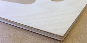
On the right you can see the five main body tubes (one with a bit cut off for experiments). This tubing is much like phenolic, but two differences are immediately apparent: the spiral grooves are deeper and wider and the tubes are finished with a gloss coating.
I planned to reinforce the tubes with a wrap of fiberglass anyway, so neither of these made much of a difference (see my 'glassing how-to video for details).
A more subtle difference from phenolic is the smaller inner diameter of the 3.9" MagnaFrame tubes. Motor hardware is a tighter fit and Giant Leap couplers are a perfect fit (as opposed to being loose to the point of sloppy in phenolic).
Centering rings that fit 3.9" Giant Leap phenolic nicely have an O.D. of 3.883" while rings for the 3.9" MagnaFrame should have an O.D. of 3.872".
Overall, my reaction to the vulcanized phenolic tube is: meh. It worked out fine, but I don't see the advantage over regular paper phenolic. Supposedly it's stronger, but I couldn't tell any difference from working with it.
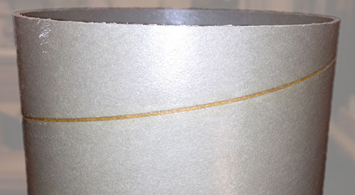
Here is a close-up of a piece of 3.9" MagnaFrame tubing showing the shiny surface and deep grooves.
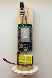
Other changes for me were that the loss of two long-time favorite products (G-Wiz and CD3) meant that I would be switching to other recovery technology. For electronics, I went with the excellent AED R-DAS v4.0 and for ejection the newly introduced Tinder Peregrine CO2 system.
The decals were provided by Sticker Shock 23 and complete the appearance of this great-looking rocket.
Aft Body
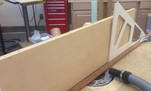
Planning out the body was the tricky part of this rocket. You have two sets of three fins: the main (aft) fins and the "sails" (mid) fins. The sails are offset from the main fins by 60°, so between both sets they radiate around at six points.
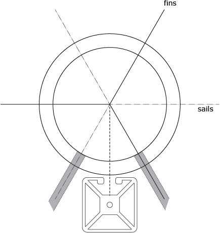
In the diagram above, I wanted to visualize the layout of the two sets of fins from the aft, and verify that a launch rail would fit between them. (Drawn is a 1.5" square mockup of a 1515 aluminum extrusion, which has plenty of room.)
Once the main fins were designed and cut, I was able to lay out the placement of the dual slots on the aft airframe section.
In this picture, a temporary strip was left at the root edge of the fin at the large cutout. (This strip will be removed once the fins are completely prepared.) The tube was marked around the circumference at the ends of the pairs slots and at three places around the tube for the fin slots.
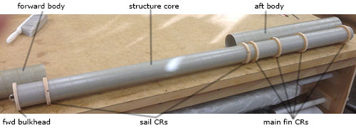
The next step was to join two 75mm 36" tubes together for the inner structure. Actually, my rocket is not unlike the Estes original, with the center (BT-20) tube providing the spine of the rocket and the outer (BT-50) tubes just the exterior for the larger-diameter sections.
In the picture above you can see how the centering rings were notched and paired to lock the three main fins and the sails in place and to align them. Also note that the sails are offset 60° from the main fins.
 |
 |
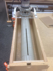
Now it was time to slot the aft section of 3.9" tubing, using my trusty fin slot jig. This worked, but the increased precision due to cutting perfectly-matching parts using CNC made the slots look crude in comparison.
I had to adjust the width a bit to match the perfectly-spaced dadoes in the centering rings. Note that there are six slots, two slots per fin, with each slot ending at the dado (slot) in the centering ring for alignment.
Once the slots were adjusted to match the dadoes in the centering rings, all surfaces were sanded again and wiped down with alcohol. It's fin installation time!
I was really hoping to get the aft (main) fins perfect, to prevent any roll during flight. So rather than installing the fins one at a time and aligning them by eye, I decided to install them all at once using guides. Above you can see the aft section with a guide ring past either end of the pairs of fin slots.
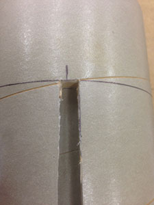
When all was ready, it was time to mix up the epoxy and go for it. Installation went perfectly, with fins fitting tightly into the dadoes in the centering rings, hardly needing the guides at all.
Once the main fins were installed, I bonded the short 3.9" airframe section that forms the most forward part of the aft airframe, notched it for the slots in the centering rings and prepared to install the mid "sail" fins.
Above you can see a test-fit of one sail into the slots in the centering rings that end the narrow section of the airframe. the sails are a perfect tight fit into the slots, so they will be kept in alignment while the epoxy cures.
On the right is a close-up, showing how well the parts fit together. The centering rings were cut on a CNC router, so everthing is coming together nearly perfectly on this rocket.
The notches in the airframe tube were cut by hand to match the grooves in the centering rings, but otherwise all the key parts were cut by machine for high precision. I'm still crossing my fingers for a flight without roll...
Forward Body
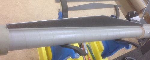
The first thing I wanted to do was laminate the two sections of body tube for the airframe forward of the "sails" (second set of fins with a solar panel design). Normally, I like to laminate my tubing anyway, but it seemed even more desirable with this tubing (MagnaFrame vulcanized phenolic).
Otherwise, the forward section is pretty straight-forward and if you've seen my techniques on other pages, unsurprising. The one new thing I learned is about a new type of hardware for use with straps: footman's loops.
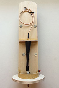
The Peregrine CO2 system has a large flange, which takes up more than half of the surface of the in-line avionics bay. Thus, I had to both move the mounting plate off-center and use dual threaded rods instead of a single spine rod. That left the issue of how to attach the recovery system to the bay.
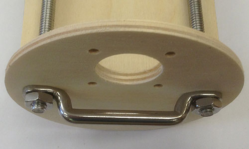
Above you can see an end of the avionics bay with the dual threaded rods and the footman's loop to bridge them. There's plenty of space to attach the bridle and the force is transmitted directly to the rods, without stressing the bulkheads.
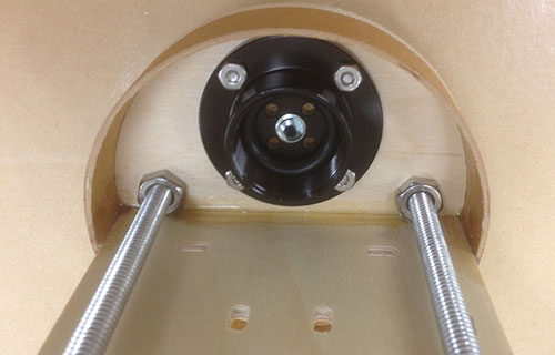
And here you can see the end from the inside, this time with the end of the Peregrine bolted to the inside of the bulkhead. It's not really that large, but when you start trying to cram in stuff, a 4" bay gets a lot smaller!
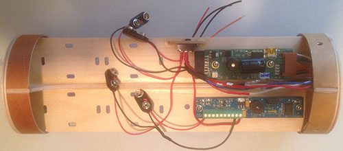
And, of course, the front of the bay, with the two altimeters installed, along with space for four 9v batteries.
Nose Cone
This rocket had an unusual nose, which isn't readily available for 3.9" tubing, so I had to make a custom one. I found this drawing of the original Estes BNC50J by Balsa Machining Services to use as a guide. Gordon Agnello turned a custom nose for me based on this drawing to fit the 3.9" MagnaFrame tubing, and I used that a plug to make a custom fiberglass nose cone.
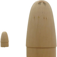
Above you can see the comparison in size between the Estes original balsa nose cone and the wooden plug. Somehow it looks a lot bigger than 4.1x upscale!
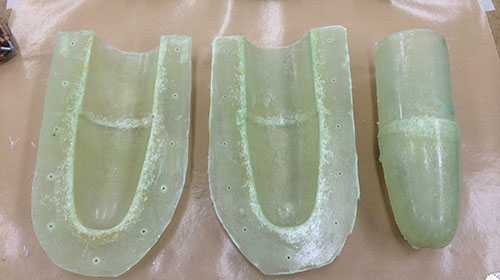
Here's the custom nose cone, newly removed from the mold. See the two-part video series to learn how to make your own.
Of course, I couldn't let that space inside the nose cone go to waste, plus I needed an attachment point for the recovery harness. So, I built a standard bay, based on a 54mm hole in the bulkhead.
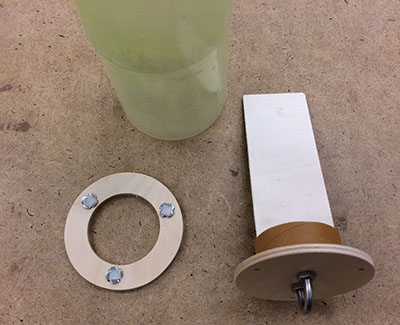
In the picture above, you can see the ring on the left and the bulkhead with the bay on the right. No mounting holes have been drilled in this sled yet, but see below where I installed a GPS tracker.
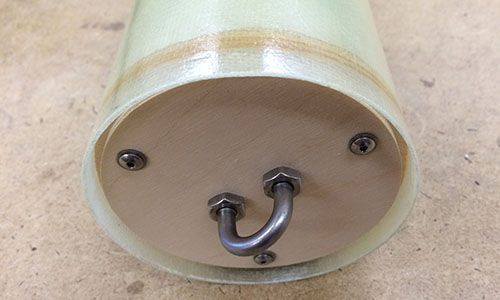
The centering ring with the three T-nuts mounted into it was epoxied into the base of the nose cone, completing both the bay and providing an attachment point.
 |
 |
And finally you can see the payload of the nose cone above: a Real Flight GPS-1.
Fins & Sails
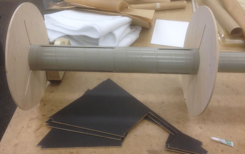
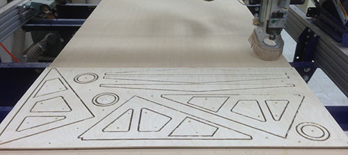
The main fins and the sails were cut at the same time, using the ShopBot alpha at my local TechShop. This first picture shows the fin cores and sails cut from ¼" plywood sheet, still on the ShopBot bed.
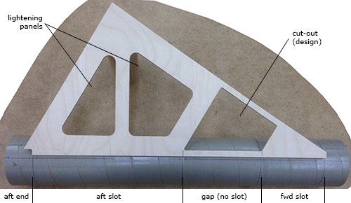
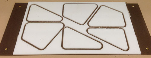
I decided to lighten the main fins a bit by cutting out two interior panels and filling them with foam. This shouldn't have a large effect on strength, since there is still a truss structure intact in the plywood core. This picture shows the panel inset pieces cut from ¼" Rohacell® foam core.
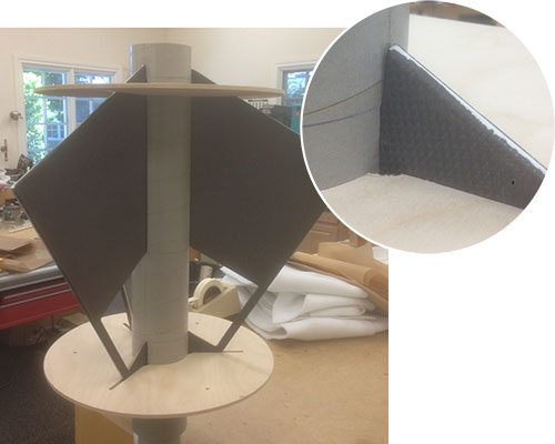
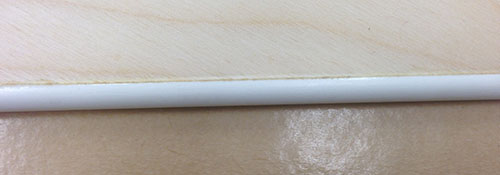
Another experiment I tried with this rocket was a new technique of fin edging. With a heavy rocket, I wanted a solid edge for the ¼" thick fins, so I decided to use ¼" fiberglass rod. However, simply bonding the rod to the fin edges would have left a large gap so I decided to use a router cove bit to route a half-radius along the edges of the fins that the rod would mate with.
Above you can see the router set-up, with a fence for the fins to run against and a rail to keep them pressed against the fence. The router is set so that the ¼" cove bit protrudes just a tiny bit less than ¼" from the table surface.
On the right you can see the coves produced on the triangular fins where leading and trailing edges meet.
Despite some tear-out of the surface ply at one grain orientation, the cove came out well and the fiberglass rod could be bonded to the fin over a large surface area (half its circumference in fact).
This also has the added advantage of not having a gap to fill between the flat edge of the plywood and the curve of the rod.
Above you can see the fiberglass rod bonded to the leading and trailing edges, meeting at a 90° corner joint. And below you can see a close-up of how the rod is socketed into the edge of the fins, making a much more secure bond than just a narrow point of contact.
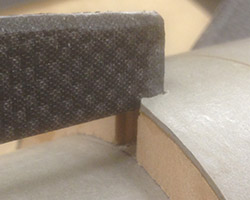
The same treatment was given to the outboard edges of the "sails" (mid fins). While much smaller, they would also take a beating during transportation and landing so it seemed wise to give them a solid edge as well.
Then, the fins went into the vacuum bag to be covered with 6oz carbon fiber to and provide a stiff and strong core over the whole surface and guarantee the stayed flat. This also married the foam panels into the plywood structure.
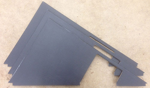
Above you can see the fins out of the bag, with the excess fabric trimmed off and the extra pieces at the bottom cut out. This is how they would be mounted into the centering ring slots on the core tube.
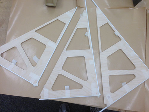
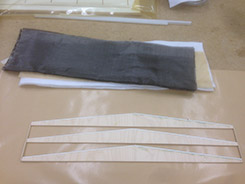
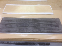
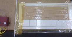
Next up was the mid fins (or sails), which were done in the same way as the main fins. The four photos below show the process of laminating the ¼" plywood triangles.
 |
 |
|
 |
 |
|
The laminated parts were left in the bag until full cure, then cut out from the larger carbon fiber lamination. (To make it easier, I tacked a piece of ¼" dowel to the ends of all three so they could be handled as a unit.)
Recovery
Despite its unusual aft section, this rocket has a standard layout and I went with a standard dual deployment recovery system based on the AED R-DAS v4.0 and the new Tinder Peregrine CO2 system.
The Peregrine is not a drop-in replacement for the CD3. First of all, the CD3 system doesn't require using the housing around the cartridge, while in the Peregrine the housing is integral. Secondly, the Peregrine is entirely inside the bay (and shorter overall), but also takes up a larger diameter because of the mounting flange on the end of the housing.
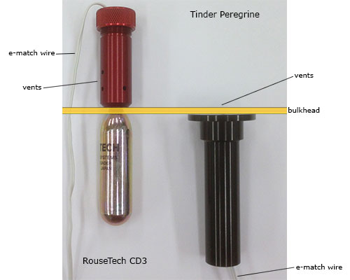
Above you can see a comparison of the RouseTech CD3 system and the Tinder Peregrine system, showing them aligned at a mounting bulkhead. If you leave out the housing, the CD3 is smaller diameter, however the Peregrine is entirely inside the bay.
Finishing
With a long 76mm MMT available, weight was not a critical issue, so I was able to do a decent job of finishing (including a heavy primer coat). The vinyl decals were made by Sticker Shock 23.