Comanche 3 Upscale
In January 2013, I got the urge to work on rockets again. I spent some time working on the my Nike-Tomahawk, but then got interested in building an upscale of the venerable Estes Comanche 3 (#1382). This rocket isn't nearly as complex as the Nike-Tomahawk or Flash Gordon rockets, which is a nice change of pace from multi-hundred hour projects.
I decided on an upscale to 3.9" tubing (4" O.D.) for a "4.123x upscale", using 54mm motor mount tubes and designed for Aerotech Warp 9 motors, particularly the short ones as the booster stages are only 12" long at this scale! This is a 3-stage rocket so not only do motors have to fit in there, I also need to get in electronics for staging. Construction started in mid-February 2013.
The Pictures
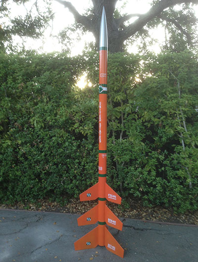
The first picture, in my back yard shortly after finishing is complete (and before any "hangar rash").
Aeronaut 2013
The rocket was easily ready for the AERO-PAC Aeronaut 2013 launch, and so that was the maiden flight. The motors used where two I599s in the booster and a J90 in the sustainer (pft, pft, sssssssssssss).
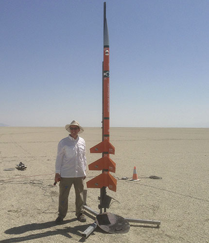
Friday morning dawned clear and windless so final preparations were made and the rocket went out to the pad. With all five G-Wiz units beeping away and the camera armed, the rocket was ready for flight. The obligatory "dumb rocket photo" out of the way, we headed back to the flight line.
Unfortunately, the ground igniter (dipped DaveyFire 28F) burned without lighting the motor, so I tore everthing down again and brought it back to camp. After testing the 2nd and 3rd stage igniters and another couple of undipped DaveyFires with 9v batteries, I concluded that somehow the system was burning the DaveyFire bridge wire without igniting it fully. So, a new set of staging igniters were made and installed (same dipped 28Fs).
After a second failure to ignite the booster motor (same failure mode), Tony Alcocer gave me one of his igniters for the first booster and it was back out to the pad for a third try (this time without tearing everything down). Thanks to Tom Rouse and Erik Ebert for their help and patience!
And it worked; all three stages lit properly. Three-stage rockets are notoriously difficult, but I had gotten mine to work; hooray!
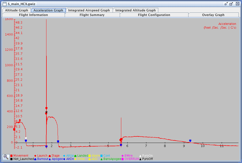
There were a few seconds of nail-biting before the sustainer lit since it took the J90 2.5s to come up to pressure. (See the HCX acceleration graph and flight summary and for details.) For the impatient, the sustainer reached 4060' (1237m) at 18.6s.
Ken Adams got some great pictures in his Aeronaut 2013 gallery and Ari put another great set up on The Rocketry Forum.
The boosters, however, turned out to be single-use. I pinned the stages together, to ensure that the second booster didn't drag separate, expecting the gasses from the motor pressurization to seperate the stages. It did, but not quickly enough to prevent the forward ends of the boosters from getting torched. To avoid this, I would need to use separation charges to make sure the boosters are well clear.
Two pictures of the rocket made it into the Aeronaut launch report in Rockets magazine (volume 7, issue 6). Thanks Tony and Ken!
The Design
First of all, the main drawing. This shows a straight-forward upscale of the Estes kit. I used the JimZ instruction archive for reference.
The biggest challenge in the design is packing everything into the 12" boosters. Since I'd decided on 54mm MMTs, that only left about ¾" of depth for electronics bays. A detailed drawing of the interior layout shows how room for staging couplers was maintained as well as the location of the electronics bay and where there was room for fin tabs.
The boosters were where most of the design challenges were. Fitting the motor, through-the-wall fin mounts, an electronics bay and the recovery laundry itself was challenging. Note that both booster airframes are 12" long.
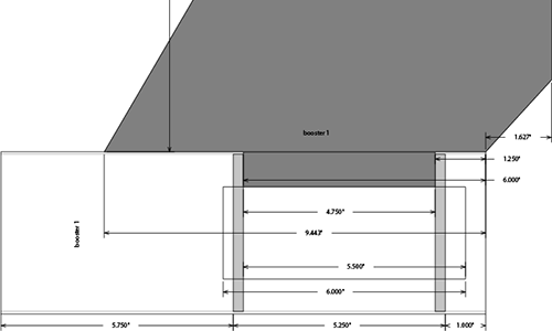
Above is the interior layout of the first booster, showing the through-the-wall fin attachment between the two centering rings. This space (between two fins) is also used for the electronics bay. (See the full drawing of all three stages.)
Above is the interior layout of the second booster, showing a similar structure to the first booster (above). Note however, that there is a space between the aft projection of the MMT and the body tube to allow for a 2" staging coupler.
And finally, above you can see the same interior layout for the sustainer. While space wasn't tight here, I needed roughtly the same layout as the second booster for staging anyway, so I kept the same design. However, I did lengthen the through-the-wall fin tabs all the way to the forward ends of the fins for maximum strength.
The decals were provided by Sticker Shock 23 and complete the appearance of this classic rocket.
Construction
Once the design had been worked out, it was time to start building! There was lots of fabrication work for the boosters so I started with them, including the aft end of the sustainer which had the same design.
Aft-Ends
After the detailed design of the two boosters and aft end of the sustainer (see interior drawing), it was time to start building.
In the photo above, you can see, from right to left, the first booster (right), the second booster (center) and the sustainer (left). Behind are the tubes with the hatches cut out and in front are the MMTs with the aft CR and motor retention installed. In the front row, you can see the hatch cover retainers (left) and the hatch covers themselves (right).
The hatches were done with a router, using a jig to get the shapes identical on each tube and making even rounded rectangular holes. The fin slots were done with a fin slotting router jig as seen above.
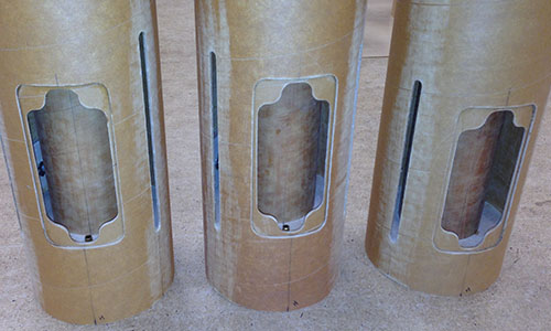
After the hatch retainer plates were installed and the fin slots were cut, I test-fit the MMT assemblies into the tubes and the picture above show the three aft ends ready for the fins to be installed.
Note the brass tube at the bottom of the second booster and sustainer electronics bays; these are necessary for staging igniters. (For this rocket, I'm using the standard method with the igniter run in through the nozzle.) Of course, the first booster does not require one as it will be lit on the ground.
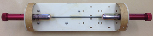
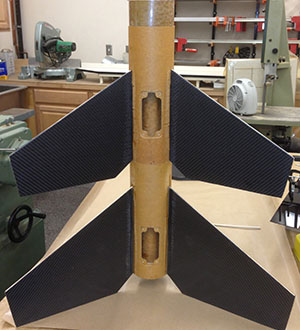 And here to the right you can see the two boosters with fins and couplers, assembled and
set on top of each other as they would be in fight.
And here to the right you can see the two boosters with fins and couplers, assembled and
set on top of each other as they would be in fight.
At the top is the 2" of staging coupler sticking up from the second booster, which matches that sticking up from the first booster, but coupled inside the second booster. (This is why the complex aft end of the second booster and sustainer; to allow space for the staging couplers.)
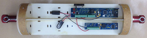
Both electronics bay hatches are facing the camera so you can see how little space there actually is for recovery. (The parachutes actually need some of the space in the staging couplers!)
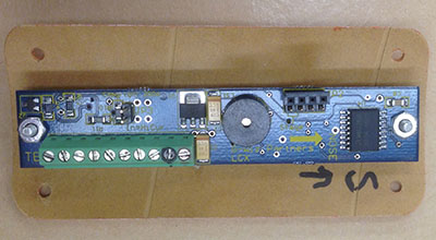
The G-Wiz LCX units screw to the inside of the hatch cover for all three aft-ends. This hatch cover is for the sustainer (third) stage, but all three are the same.
Fins
The Comanche 3 fins are more-or-less a clipped delta shape, except they are also swept back. This isn't an ideal design, but this isn't a high-performance rocket anyway. I decided to make the fins upscale-thick as well so instead of 1/16" thick balsa, they would be ¼" thick composite. (Plywood would have been easier, but then the fins would be very heavy, which is a problem for the boosters which have tiny recovery space.)
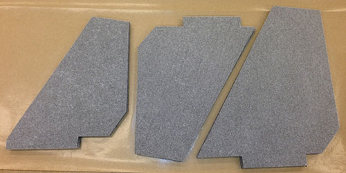
I decided to use two pieces of 2mm Rohacel foam with a single layer of carbon fiber cloth in between as the core. This produced a sandwich 0.19" thick. Templates for each of the three sized fins were cut from sheet plastic and used to cut the nine fins out of the core before the epoxy has fully cured.
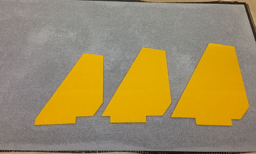
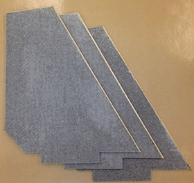
Above you can see the three templates on the core sandwitch, before cutting. Below are the nine fins in three stacks after being cut out and fully cured.
The fins were slightly undersized to allow a half-round dowel cap to be applied to the forward and tip edges to create a hard, rounded edge. This simulates rounding a single piece of wood and presents a solid surface to the leading edge (as opposed to exposing the foam sandwich edges).
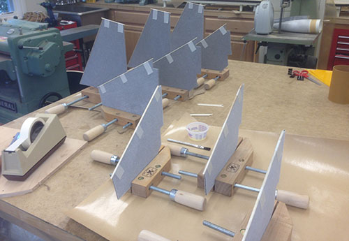
Above you can see the middle stage of applying the half-round dowel edging to the fins (the sustainer fins in the foreground and the booster fins to the left).
 |
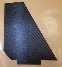 |
After edging, the fins went into the vacuum bag for a layer of carbon fiber on the outside, completing the strong and light construction. (The large fins ended up being just 150g, 5.3oz, each.)
Sustainer
The sustainer is a straight-forward "backwards ejection" design for dual deployment. The aft (motor mount) section of the sustainer is 24" long and the remainder of the long sustainer is split into two parts with the electronics bay in the center. The drogue is placed aft of center (break at the forward end of the motor section) and the main is placed forward (break at the nose cone).
The only real complexity was in building the electronics bay. As usual, I decided to make the coupler between the two body extra long and put a removable bay into it (see the overall drawing). I like this method because it allows me to completely prep the electronics and deployment charges outside of the rocket and then slide the whole shebang into the rocket without trying to route wires and charges through narrow tubes.
Above and below are the front (elecronics) and back (CD3) sides of the main electronics bay. Note that the whole thing slides into the coupler that joins the two sections of the sustainer airframe together and screws run through the airframe, couper and into T-nuts in the rings at the top and bottom of the bay.
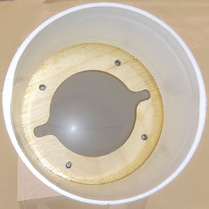
Also as usual, I decided to make the space inside the nose available for a GPS tracker (or whatever). Starting with a Giant Leap nose cone, I cut off the base (including the molded loop). Then, I built a CR fit tightly just inside the nose cone above the shoulder. (Epoxy is marginal to plastic, so I wanted the mechanical locking into the molded nose cone as well.)
 |
 |
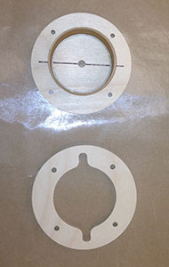
Above you can see the two parts to the bay that fits inside the plastic nose cone. The ring that bonds in above the nose cone shoulder and the hatch that is screwed to the ring. Note that there is a slice of 54mm tube in the hatch that fits into the hold in the ring and helps to support a plate for mounting whatever electronics I decide to fly here.
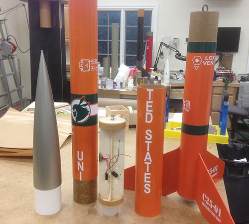
And finally, above you can see all the parts of the sustainer after finishing:
- the nose, with auxiliary bay inside,
- the forward airframe section, with coupler into which the main bay slides,
- the main bay with dual deployment CD3 units,
- the middle airframe section, that couples over the main bay,
- and the tail section, with space for a large motor.
Finishing
Because weight was a concern for this rocket (the first booster motor needs to lift the whole thing), I needed to keep everything light. As a result, I decided to do a quick-and-dirty rattle can finish with vinyl decals from Sticker Shock 23.
The body color is Krylon pumpkin (safety) orange and the nose is a darker metalic. It looks fine from far away, and the large number of decals help detract from the imperfect paint job. (Finishing is my least favorite part of building and I gave myself a pass on this rocket.)