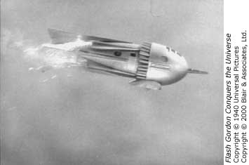
Flash Gordon
At Mudroc in June 2001, Jason Blatzheim, the motor developer for AeroTech, suggested that we do a joint BALLS project. This sounded like a good idea, but I needed something to make it unique. Most BALLS project are just big motors in heavy rockets, with the emphasis on how impressive the motor is.
It took me a while to come up with a good idea, but when I did it was a great one! Jason makes a great sparky propellant with white smoke. How about a model of the Flash Gordon rocket ship? After all, Flash Gordon's ship had four sparky, smoky motors which propelled it.
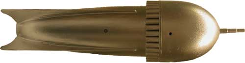
The Flash Gordon rocket ship is a pretty simple shape, a hemispherical nose and a hemi-elliptical body. The fins are very large, but run well forward to the back of the nose cone.
The engine nacelles are well forward on the rocket. In the serials, they seemed to fire straight back (although it's pretty hard to tell exactly what they are doing). The rest is just surface detail.
In 2016 we moved and all projects that had been sitting for more than five years without progress were abandoned. This one one of them.
Table of Contents
This rocket is quite complex, and this page is corresponding long, so I've broken it down into sections. This rocket was so long in the building (with long pauses while I worked on other things), that I've also added years to the subsections.
- The Pictures
- The Design
- References, 2001
- Simulation, 2001
- Fifth-size Model, 2002
- Tail Section
- Mold Plug, 2004
- The Mold Itself, 2008
- Heat Curing Oven, 2010
- The Motor Mounts, 2010
- The Body Panels, 2010
- Fins & Structure, 2010
- Nose Section
- Recovery System
- Custom Motors
- The Movies
The Pictures
 |
||
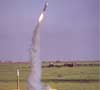
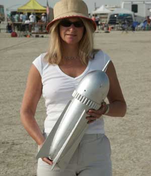
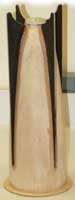
| Here my wife Renée is holding the 1/5 size model at LDRS XXI. (Being a good sport about spending the weekend at a cow pasture in Amarillo Texas.) |
LDRS XXI, Amarillo Texas
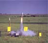
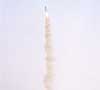
The 1/5 size model was flown at LDRS XXI to test the stability of the design. This first model was built with prototypical fins and most of the detail planned for the larger model. (You can see the rocket ready to fly in the picture above.)
I chose an AeroTech H123, since it was the lowest average impulse 38mm motor I could find. With this motor, the lift-off weight was 5.0#. The H123 pushes with about 34# of thrust for the first second, giving a thrust-to-weight ratio of about 7:1.
The measured C.G. was 10¼" from the cannon tip (7¾" from the tip of the nose). My estimated C.P. was 13½" (11" from nose tip), giving about ½ caliber of stability. (See the Design section below for more on this.)
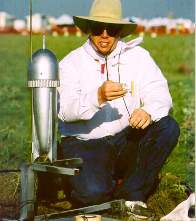
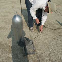
The picture above, taken by Rick Clapp, shows me prepping the small Flash Gordon model for its first flight. Even at this small size, the rocket is quite fun!
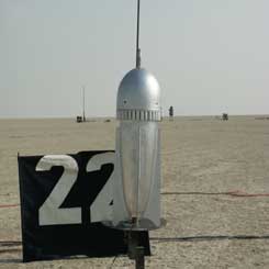
| 1: liftoff |
|
|
| 2: unstable |
|
|
| 3: arcing |
|
|
| 4: apogee |
|
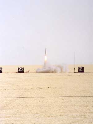
The sequence above (down the left) shows four stills of the liftoff and flight. Click on the smaller images to display a larger image on the right side. The rocket wobbled a lot on the way up, which isn't shown well by a sequence of still photos.
On the right you can see the two sections as they were recovered. (The ALTS24 beeped out 646'.)
Two of the fins broke off cleanly and there was no other damage. I'm not sure why two fins broke off like this (the rocket was recovered by children before I could find it), but my guess is it came down hard on two fin tips and sheared them off.
At any rate, this damage is no big deal since the next version will be built with larger fins anyway.
I was pleased (and somewhat surprised) that the cannon made it safely. I had assumed that this would break off in landing, but it didn't even seem to stick into the ground. (The nose must have come down on its side...)
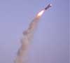
Aeronaut 2002, Black Rock Desert
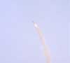
At the August 2002 AERO-PAC launch (Aeronaut 2002), I flew the small version again, this time with slightly larger fins. (See the Fifth-size Model section below for more info.)
The LDRS flight was not stable enough to make me comfortable, so I added .3" to the semi-span of the fins and made the aft end of the tail a bit more bulbous.
To the right you can see Renée holding the second version at out in the Black Rock Desert.
Despite the large fins, the model still looks good. In fact, the larger fins give a little nicer shape since the tail doesn't seem to be so small compared to the nose. (The semi-span of the fins is still smaller than the radius of the nose cross section.)
This second flight was also on an H123 for comparison purposes. The weight of the rocket did not change significantly so the only real change was the move in C.P. due to the larger fins.
 |
 |
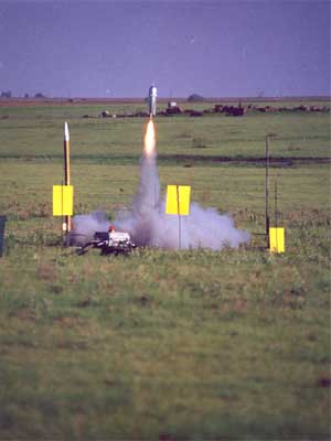
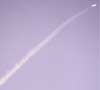
(Photos above by Renée.) This flight was a bit wobbly, but much better than the LDRS flight. I think the rocket still needs a bit more stability, but the design is certainly workable! The model flew relatively straight and up to 810' according to the Adept ALTS25.
| 1: liftoff |

|
|
| 2: stable |
|
|
| 3: wiggle |
|
|
| 4: recover |

|
The sequence of photos were taken at about ½ second intervals. The flight was a little wobbly, but it went more-or-less up. Click on the smaller images to see them in larger size on the right.
The Design
First of all, the challenge was to research the rocket. The old Flash Gordon serials have been collected and made available in DVD format. I bought Flash Gordon Conquers the Universe (12 Startling Chapters) and watched the first few segments to get a better idea of the ship.
References
|
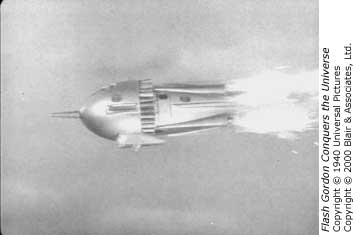
To the right are two more pictures of the ship; Another one of it flying and a shot of the outside when they landed on "Arboria." The rocket motors are really going well on the top shot. You can sort of see the white sparks and there is definitely lots of smoke. Also, note the wheel pants on the "landing gear" (presumably wheels) shown at the bottom. (I decided not to model them as they would create asymmetric drag.) The bottom photo is a nice picture from the outside, showing some external detail. In particular, it shows the steering tubes just behind the nose. (And some more details I decided not to model such as the door and window.) |
|
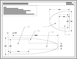
To get the dimensions, I found a spot in the movie where the ship filled the screen with a side view and paused it. Then, I was able to take measurements directly off the screen. (The measurements were scaled to result in a 10' long rocket.)
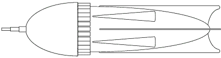
| Obviously, this isn't the most accurate way, but without the model or drawings of it, there isn't much else to be done. At any rate, it produces a result reasonably accurate to the movie. You can download a large line drawing of the rocket for yourself. Note that this drawing just shows the structural elements without any surface detail. |
|
|
Later, I discovered another great source of information for modeling fantasy rockets:
Spaceship Handbook by Jack Hagerty and Jon Rogers.
Luckily, it turned out that my drawings weren't too far off (although simplified) so
all is well.
The book also contains information and drawings on many other space vehicles that never were, and is a great source of information for the fantasy scale modeler. |

|
Simulation
This rocket is too unusual to model in RockSim (or any of the other common rocket simulators). The shape also may not match the assumptions in the Barrowman equations very well either. As a result, I was unable to determine a property center of pressure. However, I used a neat tool to check how the airflow over the body would be affected: MicroTunnel which simulates a 2D wind tunnel.
The program is designed for airfoil cross-sections and thus you can't model fins or any other 3-dimensional shapes. I entered the nose and tail sections into the program and ran the simulation. The display you see below shows the pressure flowing over the rocket body. I also overlaid the outline of the fins on the chart for reference. (Click on the graphic for the full chart with axes and summary info.)
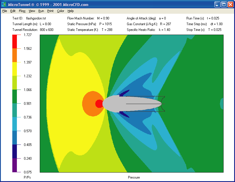
Note that while there is an extreme low pressure (dark blue) around most of the tail section, the aft end of the body is at ambient pressure (green) and much of the fin surface area exists in this region. So, there will be air flowing over the fins at the aft end, but the fins will be much reduced in effectiveness (perhaps down to a third).
This allows us to do a RockSim analysis, with a straight body tube and small fins placed aft. This is an approximation (hopefully an underestimate) of the effectiveness of the fins. RockSim places the C.P. 54% back from the forward end.
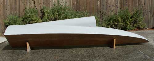
Fifth-size Model
Jason was concerned about the large nose shadowing the fins, rendering them less, or even not, effective. I thought it would be OK, since we were keeping the speed low. But, when I couldn't even model the shape properly in RockSim, I agreed that a smaller model should be built to test the stability.
I decided on a one-fifth size model (2' overall length) as an easy-to-build size. The main advantage of the smaller size is that the body and nose can be turned out of balsa, making the construction much easier.
|
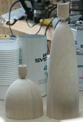 |
Above, you can see the plans I drew for the smaller version as well as the turnings that came back from San Francisco Wood Turning.
 |
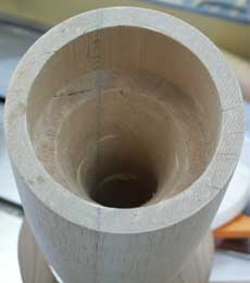 |
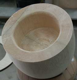
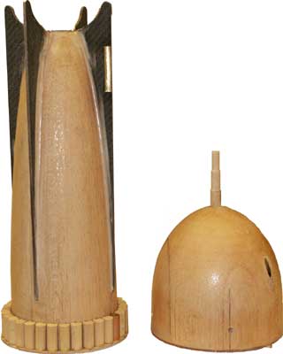
Of course, the turnings just supplied the overall shape as solid bodies. I next had to create a hollow in the nose for the recovery electronics. Also, I had to drill through the tail for the motor mount tube and create a hollow at the front for the parachute and bridle. (This took most of the afternoon of Saturday June 29, but I wanted to fly the the model at LDRS XXI two weeks later.)
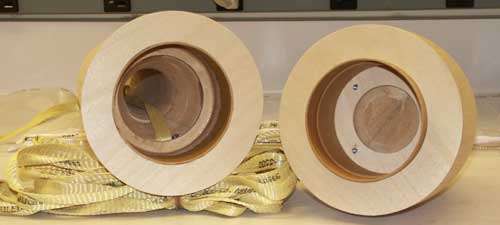
In the picture above, you can see how the nose and tail mate together to form the whole body and where they open for recovery. This is more or less how the full-size one will open, although it will use several tubes and/or pins instead of a single 3.9" tube and coupler. Note also how the nose section (on the right) includes an electronics bay. (A cover plate screws on, sitting inside the coupler and on top of the tubing section.)
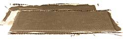
Next up was forming the fins. I decided to use 1/16" plywood laminated with carbon fiber and 4oz. fiberglass on each side. This is a quick and easy layup that produces a very strong and stiff fin without becoming too thick. (The fins on the rocket are much longer than on most rockets.) Above you can see the two fin blanks (to make two fins each) under vacuum pressure using my trusty FoodSaver.
 |
 |
|
Above left you can see the fin blanks as they came out of the bag.
(Each blank was cut in half lengthwise and the each made the straight edge of
two fins.)
Above right you can see the fins cut out and roughly shaped to match the curve of the body. (The four fins were stacked and cut to match a paper template.) To the right you can see the aft body section with the epoxy applied. (I used CyA to tack the fins in place and then used epoxy for the permanent bond). After this, cosmetic fillets were applied to smooth the transitions and the edges of the fins were shaped a bit. |
 |
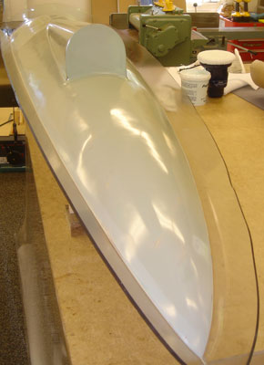
Above you can see the two body sections complete. Now all that remains is setting up the recovery system and a quick paint job.
 |
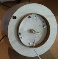 |
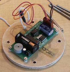
Here is how the electronics bay works in the nose section. An Adept ALTS25 is mounted to the electronics bay cover plate. wires to arm the ALTS25 are run out through one of the side vents and the electric match wires are run out through the plate. The picture on the right shows the nose section ready to attach to the bridle.
And on Monday, July 8 the small version was ready to fly just in time for LDRS XXI! As detailed in the Pictures section above, the flight at LDRS wasn't stable enough to make me comfortable. So, I decided to replace the fins on the model with slightly larger ones.
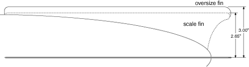
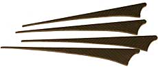
In the drawing above, you can see the larger fins relative to the scale fins. Note that the larger fins have about 4½ sq. in. more area than the old ones, even though they are only 0.35" larger in semi-span. Also, the extra area is farther away from the body and at the aft end with the larger tip.
Tail Section
The full-sized rocket was built out of fiberglass shells. This is the only practical way to make a rocket this large and with this unusual a shape. Nothing standard comes even close for the basic body shape.
Mold Plug
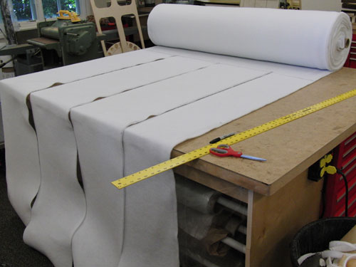
|
The first thing to do was lay out the tail section.
To create a fiberglass (negative) mold, one needs to start with a (positive) plug.
The plug is a mock-up of the surface of the desired part,
made in whatever way is easiest.
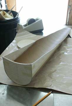
I first made a drawing detailing the curvature of the tail section, from which the mold plug could be formed from wood and fiberglass. |
|
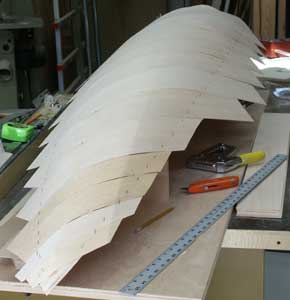
The start of building was to create a quarter-section plug out of wood. First two pieces of ¾" plywood were joined at a 90° angle to create the flat edges of the quarter slice. Then quarter-circular ribs and curved-top rectangular stringers were cut out of ¼" plywood and built inside.
 |
 |
In the pictures above, you can see a batch of stringers stacked up with the paper template on top, ready to be cut out on the band saw. On the right, you can see the first three quarter-circle ribs laid out with the end stringers in between.
Once all the ribs and end stringers had been installed, the excess plywood was cut away and the edges sanded to a nice slope to create the outline of the quarter plug.
In the picture on the right, you can see the quarter plug cut and sanded to shape.
Note that all the circular ribs are in place, separated by the outside stringers. More stringers will be added between the ribs to maintain the full shape and support the balsa sheeting.
Each of the ribs had to be cut a different radius and its curved edge beveled to match the angle of the stringers at that point.
Each set of stringers was a rectangle with a curved top to match the appropriate edge profile between those two ribs.
Everything was fastened together with white glue and screws and small legs were attached to allow the plug to sit upright.
 |
 |
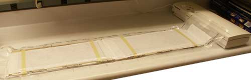
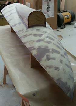
Once the structure was complete (above left) with all stringers, balsa sheeting was applied to create the surface (above right).
Finally, two layers of 9oz. fiberglass tape (6" at the large radius and 4" toward the tip) were applied to create a hard surface and give some body for sanding and smoothing.
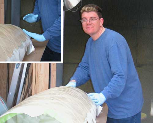
My wife Renée took the pictures above of me laying up the fiberglass. This was a pretty easy layup since it's a large piece and the fiberglass tape is easy to work with.
 |
 |
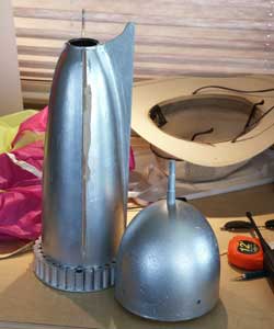
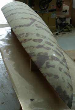
Once the fiberglass was cured, it was time to sand it smooth (always a nasty job). Then I trimmed away the excess balsa sheeting and fiberglass to create the final shape of the plug body (above left). Also, the shape for the engine nacelle was created from a 6" body tube and plywood sheeting (above right).
 |
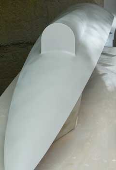 |
The final steps for the plug were to attach the nacelle and finish the surface. Above left is the plug with the nacelle attached and all major surface holes filled. Upper right shows what it looked like after several days of priming, filling and sanding. (This is the last coat of primer; whew!)
After the last coat of primer comes more sanding! (Isn't there always more sanding?) This sanding isn't that bad, though, since it done wet. The primed plug was wet sanded with 150, 220, 320 and 400 grit until it was completely smooth. (Photo by Renée Coker.)
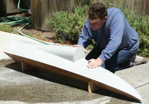
And above you can see the plug sanded and ready to create the mold. That was a lot of work and I haven't even made a part that will be on the rocket yet!
The Mold Itself
Here there was a four-year interlude where I worked on other projects. In July 2008 I resumed work where I'd left off: making the mold.
Because this was such a large surface, I sanded this plug all the way down (up?) to 800 grit. Then, I used a small buffer to apply mold release wax to the plug surface, twice.
 |
On the left is the plug, with the acrylic edges installed.
At this point, the plug had been waxed, the edges filled with clay and
three coats of mold release sprayed on.
Below is a close-up of the tip (at the aft end of the rocket). Note how the edges are filled with clay and the acrylic provides a defined edge for the mold. | |
 |
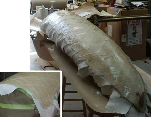
Once the plug was ready, I applied a gel coat layer. In this case, I just used thickened epoxy with a coloring agent added. Once the gel coat had partially hardened, I applied the fiberglass cloth over it, starting with 4oz. and working up to 10oz. Because of the complex shape, I had to use pieces about 12" square and overlap them in various ways. The part around the engine nacelle required particular care.
 |
 |
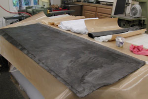
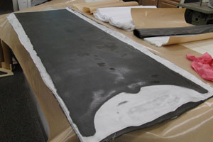
After curing over night, it was time to part the piece from the mold. I had been worried that this would be difficult, since there is so much surface area, but it actually popped right out once wedges were worked in around the perimeter.
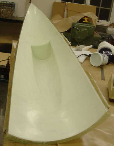
The picture above shows the freshly-parted mold. It turned out very well, with only one small void to repair. I probably could have let the gel coat cure a bit longer as there were a few areas of cloth print-through, but it doesn't really matter for a mold. (The mold looks greenish because of the epoxy and fiberglass underneath the gel coat.)
Heat Curing Oven
I realized that base drag would cause a lot of heat from the motors to splash back onto the body sections. Thus it seemed necessary to use a high-temperature epoxy. There are several choices, but I've used Cotronics epoxies before and their Duralco 4460 seemed a natural choice as a laminating epoxy. However, that product requires an elevated temperature cure (350°F), which meant that I had to build a heat curing oven.
The oven itself isn't hard; it's basicaly just pieces of rigid insulation taped together into a box. Heat can also be easily produced using standard indandescent heat lamps. The difficult part is the accurate temperature control and air circulation.
For temperature control, I found numerious kiln controllers on ebay at very reasonable prices and bought one. These units are basically solid state relays which turn on and off at specified temperature points, as measured with an external thermocouple. (The unit I ended up using had the SCR separate from the controller.)
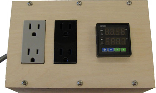
Above is the completed box, with the controller on the right, a switched outlet (black) in the center, and an unswitched outlet (gray) on the left. The switched outlet will be for the heat lamps and the unswitched outlet for the circulation fan.
Since the oven box is pretty much a temporary structure (cheaply and easily made from rigid insulation and too large to store easily), I decided to put all the interesting stuff into reusable ends and build the foam box around them.
In the picture above, you can see the 20" square oven ends. The one on the left has two light sockets for the heat lapmps. The one on the right has a 110VAC electric fan to circulate the air through the box.
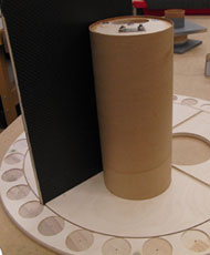
The Motor Mounts
The one part of these body panels which isn't just cosmetic is the way the four motors mount. Because the motors are in engine nacelles which project from the body, I needed to create a framework which supported the body and transferred the thrust of the motors to the framework, not just the body.
I have a membership at the TechShop, where I cut the pieces from ½" plywood on the ShopBot CNC router. This created a frame which would mount inside each body section and also bond into each corner of the fin structure. Each one incorprates a 98mm MMT in the form of a 28" tube as the core of the structure with custom cut plywood bulkheads at each end which will be embedded into the body parts as they're laid up in the mold.
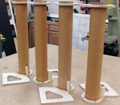
These parts have several functions. Of course, they need to be motor mounts: transferring the thrust of the motors in flight and providing a way to retain the motors in the body. However, they also need to maintain the alignment of the tube within the engine nacelle. And finally, they need to provide a secondary attachment between the body shell and the fin structure.
Above you can see one of the MMT assemblies placed in the mold. When the body shells are laid up, this piece will not only anchor the MMT to the body, but it also provides a bracket which will bond to the inside of the fin structure.
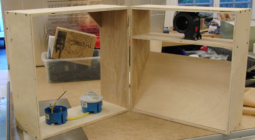
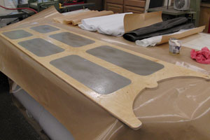
The Body Panels
Finally everything was ready to lay up the body panels. These would use Cotronics Duralco 4460 high-temperature laminating epoxy instead of the Aeropoxy PR2032 I use for most laminating (such as the fin structure).
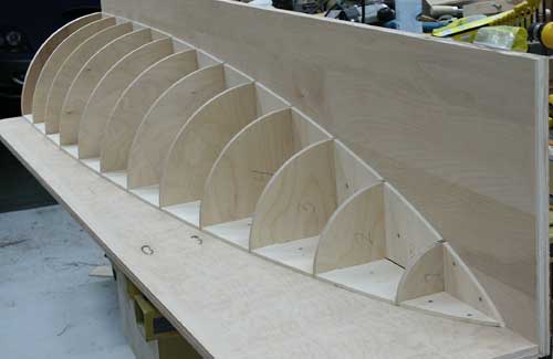
Fins & Structure
The fins are not attached to the shell as normal rocket fins are mounted to a body tube. Instead, the fins create a X-shaped structure inside and the shell is in four quarters that fit between them. This makes the fins the real structure of the rocket, and the fiberglass pieces just form the body shape.
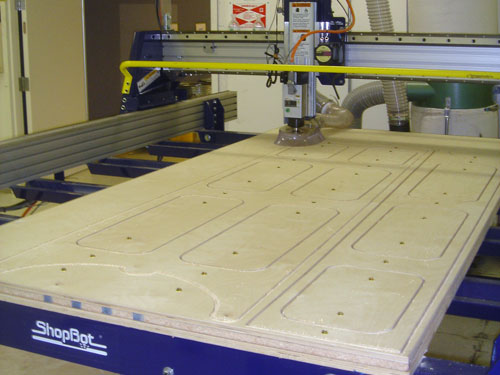
I have a membership at the TechShop, so the obvious way to cut these plywood fins was on the ShopBot CNC router. Below you can see a close-up during the cutting of one of the half pieces.
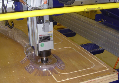
This machine is amazingly accurate and makes short work of complex shapes! In the photo below, you can see the center (double) fin and one of the side (single) fins cut out of a full plywood sheet. (Brass screws hold the pieces in place during cutting.)
Aside from the curved shapes of the trailing edge of the fins, I also wanted to lighten the weight of the fins by cutting large panels out of the interior of the ½" plywood. These are filled with foam and then the whole surface is skinned with carbon fiber and fiberglass.
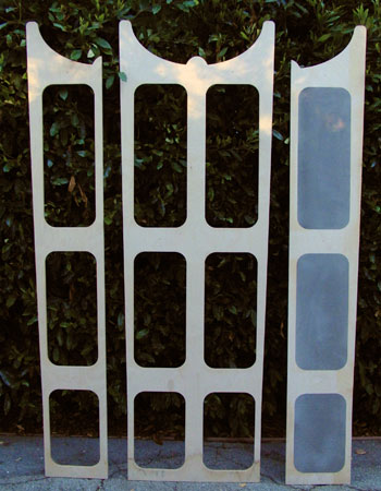
In the picture above, you can see all three fin pieces, which will be assembled into a cross with the two single-fin pieces butting against the center of the double-fin piece. The single-fin piece on the right already has the foam panels installed.
I decided to complete one of the smaller single-fin (half) pieces first since these were such large parts. In fact, I hadn't really thought about just how large these parts were until I started cutting out the materials for vacuum bagging them.
The release and breather were cut to 16" x 82" to comfortably cover the widest and longest dimensions of the "small" fin core. My big worktable isn't large enough to cut the pieces off the breather roll in one go!
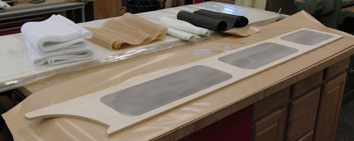
Here are the components ready for lamination, from right to left (in order of application): 5.7oz carbon fiber for stiffness, 4oz fiberglass veil, release film and breather.
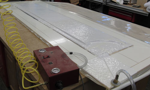
It even took a lot of epoxy to wet out the part and the four layers of reinforcement (two each side), but finally the part was in the vacuum bag. (I'm actualy using a veneer press for this large part and to make sure it cures absolutely flat.)
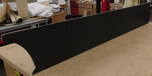
And finally on Labor Day morning I pulled the first fin out of the vacuum bag and trimmed the edges. It's hard to photograph carbon fiber parts, but it looks beautiful with the twill weave fabric. The second half-fin followed and finally the center (full) fin, as seen below.
 |
These were wet hand lay-ups, followed by vacuum bagging in a veneer press with a baseboard.
I like to wet out the core first, then apply the cloth dry since it's so much easier to manipulate dry cloth. Here you can see the core wet out for the first cloth layer. |
|
 |
Carbon fiber cloth is always a joy to work with, but rolling dry cloth onto a wet core
is particularly easy.
Once the cloth is stuck down and smoothed out, I brush on more epoxy to fully wet it out. It's important to have no dry spots, and excess epoxy will be removed by vacuum bagging. |
|
 |
Once the carbon is wet out, it's time to apply the veil layer.
Here I'm using 4oz fiberglass cloth.
The fiberglass makes any remaining dry or overly wet spots obvious. I first make sure all the fiberglass is transparent, then blot up any excess resin with wadded toilet paper. |
|
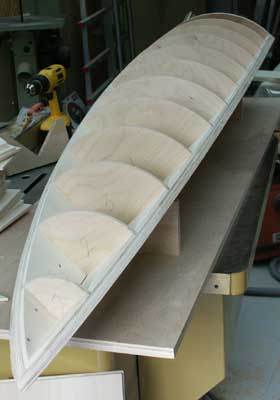
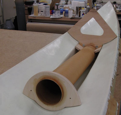
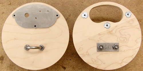
The rocket breaks at the widest point, between the tail section and the nose piece. On either side of this break are two center bulkheads. The center aft bulk bulkhead has slots for the fins, holes for the recovery bay tubes, a slot for the quarter body shells and holes for the cosmetic steering tubes.
 |
 |
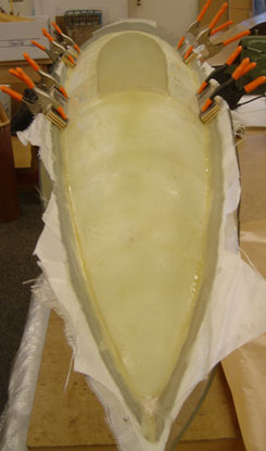
Above you can see the center aft bulkhead, with all the cuts for the various parts. On the right is a dry-fit of one of the half-fins plus a recovery bay tube assembly. I vacuum-bagged carbon and 4oz cloth the forward (open) side and 4oz cloth to the aft (mounting) side for extra bond strength.
 |
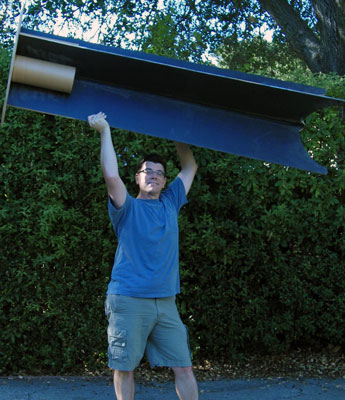 |
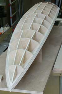
Finally, it was time to mount the fins to the center aft bulkhead. On the left you can see the epoxy curing as everything is clamped into place. On the right, you can see me holding the superstructure aloft, showing off the advantages of building light!
Nose Section
Since there was only a single nose piece, I decided to make it one-off using Styrofoam with a fiberglass shell. (We did a lot of this on the N1 project.)
Recovery System
Since I didn't know exactly how much the rocket would weigh, I needed to keep the recovery system flexible. (Jason and I planned on 50-60lbs. for motor design purposes, but I thought it would be lighter when finished.) Partly for this reason, and partly because I like multiple 'chutes, I decided to use multiple circular parachutes, and bring the nose down on a separate parachute.
Tail Section Recovery
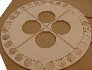
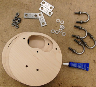
The main body of the rocket has four 6" x 13" recovery bays, one inset into each corner made by the fin structure. The electronics mount through the bottom of each bay, making them into parachute cannon. The bottoms are standard ½" plywood (also cut out using the ShopBot CNC router) and the actual mounts for the G-Wiz computers are cut out of 0.100" aluminum sheet on the TechShop's Techno CNC router.
 |
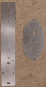 |
Above left you can see the parts for the bottom, which is a standard HPR bulkhead assembly, other than the kidney-shaped cutout for the electronics mount. Above right you can see the two main pieces of the mount. The oval place mounts over the cutout in the bottom and the rectangular piece hangs down from it. (They join with a custom cut piece of aluminum angle, not shown.)
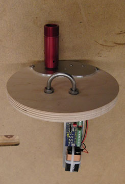
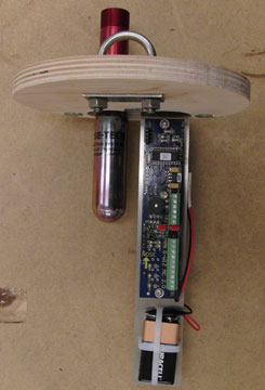
Above you can see the assembled bottoms showing how the electronics mount top fits inside the bottom and is fastened using three machine screws into T-nuts. Below you can see how the altimeter (a G-Wiz MC2) is mounted and wired up to a Rouse-Tech CO2 ejection system.
 |
 |
These plywood bulkheads mount into the bottoms of the four parachute cannon, which allows me to use any number of parachutes from one to four, and even a combination. (My preliminary plan is to to deploy one at apogee and a second of the same size at a lower altitude.)
Nose Piece Recovery
Because this rocket is so large, I wanted to recover the nose separately. Also complicating things is the stepped conical antenna at the front. Bringing it down with a parachute cannon (as used for the body) would certainly break this off, so I needed to deploy the parachute forward from the body split point.
Custom Motors
The pièce de résistance for this rocket was to be the motors. In fact, this was a large part of the initial impetus for the project when Jason Blatzheim and I started discussing the rocket. They needed to have white smoke and sparks to simulate the chemicals used by the special effects in the serial.
White smoke and sparks is a difficult combination. The usual mechanism for making sparky motor is to add metals which burn outside the motor in the exhaust plume. Unfortunately, these also result in black smoke. I needed to come up with a high-aluminum formulation for the white smoke and use a metal which didn't produce dark smoke.
The Movies
Just for fun, below are some more stills from the movie.
| Title card from "Flash Gordon Conquers the Universe." |  |
| Inside Flash Gordon's rocket ship. | 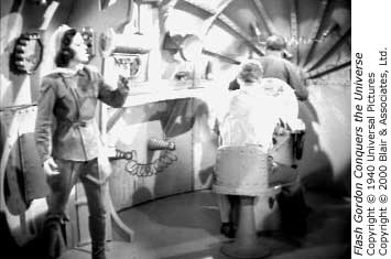 |
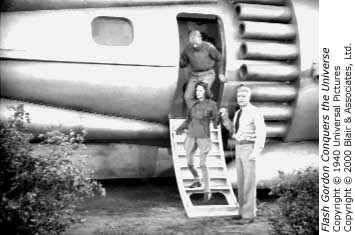
| The three main characters of the show: Dale Arden, Flash Gordon and Dr. Zarkov. | 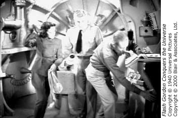 |
These old serials are really awful, but they are entertaining in their own way. 1940 was a very different time and even though there were dramatic tensions in the world, these serials still show a naivete and optimism which you don't find today. Pick them up on DVD; they are worth watching.
Tom Aldridge has put together a detailed analysis of the Flash Gordon serials for those who are interested in the series itself: Flash Gordon and His Universal Serial Compatriots: A Critical and Sentimental Perspective.