ARLISS 2008 (Two 'Fer)
Some members of AERO-PAC, organized by Tom Rouse, worked with Professor Bob Twiggs of Stanford to build rockets to launch student satellites from amateur rockets at the Black Rock Desert. For more information about the program, see the ARLISS web site. The first ARLISS launch was held on September 11, 1999 after much planning. Two teams from Japan, a team from Arizona and a team from Redwood City, CA each built three "can sats" and the ARLISS team provided four rockets to launch them. I helped out here and there with construction, but mostly I took pictures.
I participated as a flier in the second (2000), third (2001) and fourth (2002) years, with my first ARLISS rocket, ARLISS 2000 (Coker's Cans) and in 2004 and 2007 with my second ARLISS rocket, ARLISS 2004 (3UP).
The upcoming 2008 launch will mark the 10th year of the ARLISS program. My ARLISS 2004 rocket suffered minor damage, but was easily repairable. However, I wanted to experiment with a rocket capable of flying two M carriers at once. Tom Rouse and I came up with the design for the "Two 'Fer", which would carry two ARLISS-M carriers at once and I decided to build one for the 2008 season.
This page also contains a section on making an ARLISS-M carrier and my alternate method for mounting a Rouse-Tech CD3. Also of interest is my attempt to use MonoKote on this rocket.
The Pictures
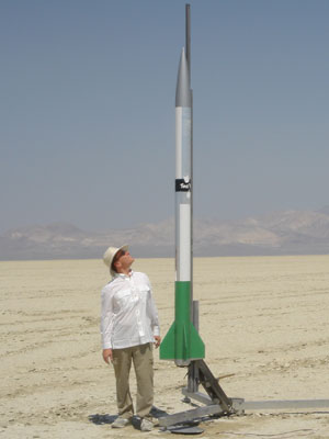
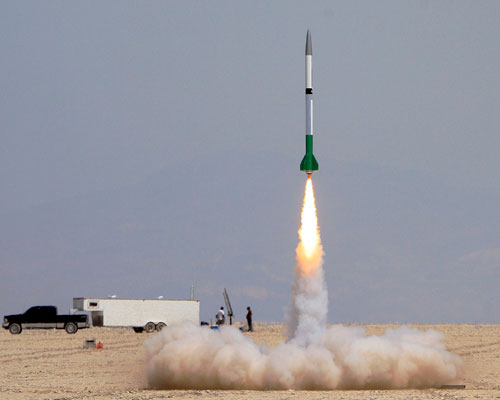
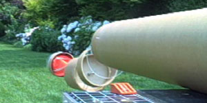
First launch, July 2008, at Mavericks in Black Rock, Nevada. Photo above by Ranny Mitchell, below by Steve Jurvetson.
Mavericks 2008
The first test flight of the Two 'Fer design occurred at the Mavericks launch in July 2008. This was a test with two carriers, although both were empty this time.
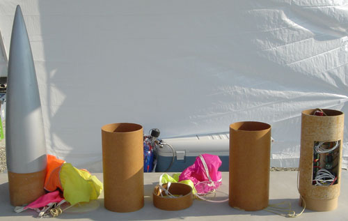
Above are the various pieces that went into the payload section, from the nose on the left (standarnd ARLISS style) to the payload section on the right. Also, here is a short clip of me loading the carriers.
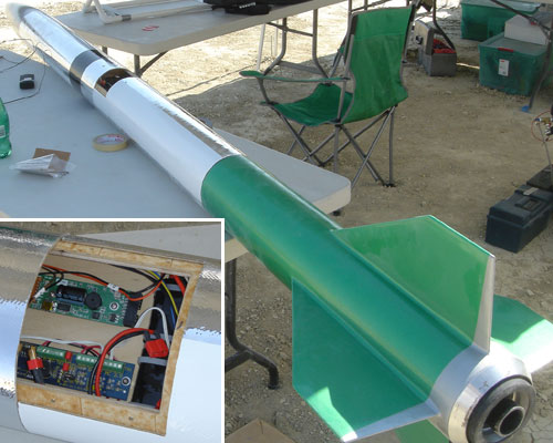
You can see the extra length in this shot of the assembled rocket (125" overall). The inset also shows the electronics bay with the hatch cover still off. (Alert readers will notice that I've switched to lithium-polymer (LiPo) batteries and Dean's connectors for this rocket.)
Ranny Mitchell helped me carry the rocket to the pad and took the traditional "dumb rocket picture" at the top of the page. Liftoff and flight were normal, although the rocket "swam" a bit, due most likely to the extra length (there was almost no wind). The lift-off weight was 39#, pretty much right in line with the standard version (although this was without projects in the carriers). The G-Wiz MC2 recorded an altitude of 11,283' and the R-DAS Tiny recorded about 10,750';
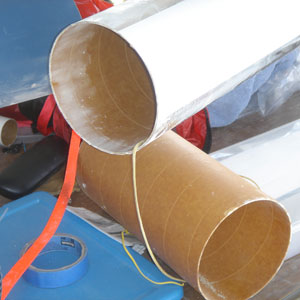
Ranny and I went out to recover the rocket, and found the forward carrier first, along with its parachute, ring and plate (to the right).
Next, we found the nose cone with its parachute and plate (below). So far, just like a normal ARLISS deployment in a line downwind and the various parts not too far apart, with the only difference being the extra carrier with its recovery.
Next up was the booster, just as one would expect. Although, somehow the motor had kicked out, tearing the AeroPack retainer with it!
Below is a close-up showing how the screws were torn right out of the T-nuts in the aft centering ring. How this happend without any apparent damage to the rocket itself is a bit of a mystery.
We continued on, expecting to find the payload section close to the others. However, no matter how far we searched, there was no sign of it. Ranny and I went searched the down-wind area for at least 5 miles with no luck. Further attempts (including a short ride in a small airplane) still came up empty.
Finally, someone found the payload section, not very far from the away pads. It had apparently come down much closer to the pad than any other section and we'd driven right on by each time, never expecting it to be so close!
I didn't see the payload section freshly landed, but was assured that the carrier had been fully ejected when recovered. (The photo on the right was as the rocket was left for me by an unknown benefactor.)
Despite not having a nice photo on the ground, I felt confident in taking this as an initial success for the Two 'Fer design.
The Design
On the way back from the 2007 ARLISS launch, Tom Rouse and I discussed how we could keep the time-tested ARLISS deployment design, yet accomomdate two student projects at once. Carrying dual carriers would make flights cheaper for the students, as well as reduce the number of flights necessary, making the launches easier on the fliers. Thus the "Two 'Fer" project was born.
Of course, the deployment couldn't be exactly the same since only the first (aft) carrier would be tethered to the rocket. My eventual design assumed that the second (forward) carrier would require the project to be a loose fit and slip out without the sharp jerk from the carrier reaching the end of the tether. (The second carrier has its own parachute, which will orient it so that the project will slip out due to its own weight.)
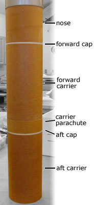
On the left, you can see the stack which replaces the single carrier in the traditional design.
The first thing to note is that the Two 'Fer design is much longer than a traditional ARLISS rocket. (My 2004 version kept the traditional overall length, even though switching to a backwards-ejection setup.)
From the bottom, the aft carrier is the traditional ARLISS configuration, resting on top of, and tethered to, the electronics bay. On top is the ¼" acrylic cap (white band). This part of the design remains the same.
On top of that is a 2" double coupler section, which contains the parachute for the second (forward) carrier. Note that the cap for the aft carrier is tethered to the forward carrier and the parachute is connected to the tether.
Next we have the second carrier, again another standard carrier, just tethered to the ring, and aft cap with its own parachute instead.
Finally, we have the forward cap, tethered to the nose cone and its parachute (as in a traditional ARLISS rocket).
Basically, the aft cap, ring and parachute, along with the forward carrier, are inserted between the usual carrier and the nose cone. This lengthens the payload area by 14¼" (12" for the carrier and 2¼" for the cap and ring section).
I also decided to increase the length of the electronics bay from 8" to 12". This is a large increase, but allowed me to accommodate a CD3 unit for carrier ejection, as well as creating a nice well which would make it easier to pack the aft carrier (since the tether would fall into the well without getting between the walls of the electronics bay and carrier).
The increase in payload space for the second carrier, plus the increased length of the electronics bay meant that the Two 'Fer was significantly longer than the standard ARLISS rocket. See the overall drawing for the details of the airframe layout.
Also, see the electronics bay drawing for details of the lengthened design and mounting of three CD3 units. The electronics bay bulkhead drawing shows how the three CD3 units were squeezed in and the mounting bracket required.
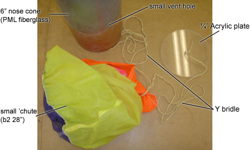
The nose cone has its parachute and Acrylic plate just like a standard ARLISS rocket:
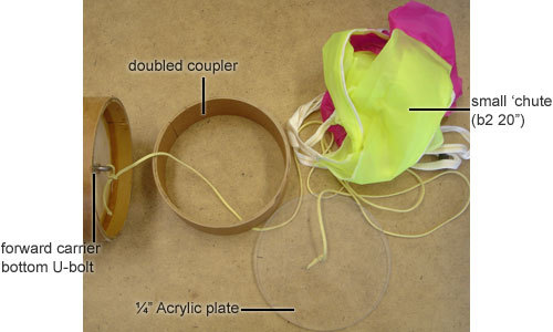
The first (forward) carrier needs a parachute and the second (aft) carrier needs a top plate as well. These are incorporated with a small doubled coupler section to contain the parachute and bridle:
So, in so far as possible, the deployment and arrangement of the the carriers matches the standard ARLISS design.

The second (aft) carrier is attached to the payload section as usual; the first (forward) carrier is attached to a separate parachute for orientation after deployment.
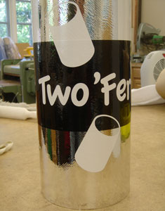
However, as you can see on the right, the Two 'Fer is significantly longer than my prior (ARLISS 2004) payload section. Instead of 48" long, this payload is 68" long.
The payload section is actually two pieces, which couple on the electronics bay. This worked out well for me since the full-length carrier allows much more room for electronics, even the ever-lengthening G-Wiz flight computers.
The coupling is closer to the aft end; the center of the payload bay is at the bottom of the chrome-colored ring just below the logo. See the overall drawing for more info.
20" extra in this rocket changes the length/diameter ratio from 17 to 21, but hopefully the in-flight performance won't be too much altered. There is some risk of coning, especially with the generous fins, but 21 L/D is still within the normal-shaped envelope.
Ejecting Two Carriers
The big question was would a CD3 generate enough gas to eject two carriers from this overly long payload section. So, I set up a test with a 25g and a 38g CO2 cartridge. Note that for this test the carriers were empty and the rocket was on its side. In actual use, the carriers would have student payloads in them and the rocket would be nose-down at deployment.
In the first test, the 25g cartridge didn't quite have sufficient volume to eject the second carrier. The second test, with the 38g cartridge did eject both carriers, but not with as much energy as I had hoped for. It should work, but won't provide the same blast that black powder does for a single carrier.
|
Test 1 25g |
 |
Test 2 38g |
View the two short videos (QuickTime format): test #1 (25g cartridge) and test #2 (38g cartridge).
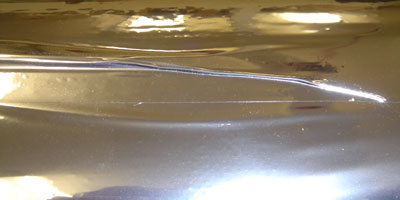
Finishing With MonoKote
I'd seen reports of people covering rockets with MonoKote® film, but had never tried it myself. Always up for an experiment, I thought I would give it a try.
One of the exciting things about MonoKote is the number of colors available, including neons, metallics and pearls. I decided to try chrome and bought a roll of it along with the basic set of tools (iron, sock, heat gun and glove).
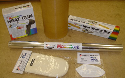
The first thing I did was get the roll of MonoKote and the necessary tools as you can see in the picture above. The heat gun at the upper left is for heating large areas to activate the adhesive. The sealing iron in the upper right is for tacking the film initially and for sealing edges. The mitten is to protect your hand when smoothing out the heated film and the cotton sock covers the shoe of the iron to protect the film. Not seen is the instructional video, which shows the basic techniques.
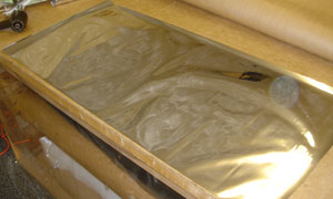
On the right you can see the sheet of chrome MonoKote film cut and ready to wrap onto the airframe tube for my first attempt. This is the top view, after the film has been cut to size. There is a clear film over the adhesive side that must be removed before application.
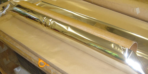
For my first attempt I planned to wrap it into the tube, much like one would do with fiberglass reinforcement. In the picture below, you can see one edge of the film lined up with a guideline drawn on the tube. I tacked the top edge to the tube, then rolled up the tube in the MonoKote.
This technique doesn't work well, because the film doesn't stretch when cold and you end up with air bubbles which can't be removed because the film isn't flat against the tube everywhere. The first attempt was a failure and I removed the partially adhered film.
For the second attempt, I decided to use the heat gun and the mitten to bond the film full width and slowly work around the tube. This way, I could constantly smooth out the wrinkles to the unbonded part and to the ends of the tubes.
This seemed to be working well, until I got around to the last few inches of film. The film sticks to itself much better than to any other surface and it once it touches the lower layer, there is no breaking apart the bond without removing the lower layer.
Covering a tube is harder than one would think! I thought I would try the hatch cover, since that was a small part which didn't require wrapping around a tube.
On the right is the completed hatch cover. This picture pretty much says it all, but it must be emphasized that MonoKote is not a "quick finish". First of all, it shows surface imperfections much like paint does. In particular, you can see the grid pattern of the fiberglass reinforcement clearly. (For this rocket, I used 1 layer of 6oz. fiberglass.)
MonoKote definitely has possiblities in Rocketry, but unless there is a better solution to handling the overlap when wrapping a tube, it is probably best for trim and non-cylindrical pieces.
Also, the same surface preparation must be done as for paint. The big advantage is the difficulty of getting a perfect metalic like this chrome film with paint. While not easy to use, MonoKote merits further experimention.
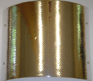
After my difficulties with the MonoKote film, I decided to try the "trim sheets". These are 5" by 40" sheets of the same material, but with a pressure-sensitive adhesive rather than a heat-activated adhesive. Of course, the sizes are too small to cover an entire 6" rocket, so I decided to use a checkerboard pattern of white and chrome with a band of black for accent.
Like the heat-sensitive film, the trim sheets show the quality of the underlying surface, but the smaller sizes and lack of need for a heat gun make applying it easier. So, even the trim sheets don't make for a "quick finish" solution, but at least I was able to minimize the wrinkles by working with smaller pieces.
Again, the grid pattern from the fiberglass reinforcement shows through. I would rate this as mediocre, although most of that is due to the lack of a smooth surface before applying the trim sheets. These brilliant colors and metalics definitely provide some good options for finishing, but take just as much prep work as painting.
And finally, the thing I'd feared would happen with an adhesive film that was left to run off the ends of the tube: there was some peeling up at a corner.
On the right, you can see a small corner peeled up. This is on the leading edge of the airframe section where it couples on the electronics bay. Moreover, this is actually a corner between the forward edge and the hatch cover cut-out so it's doubly exposed.
There was only this single spot, and it was at the corner at the electronics bay hatch cut. So, I would say that the MonoKote is pretty tough stuff.
An Alternate CD3 Mount
Tom Rouse is constantly improving his CD3 CO2 ejection system and recently introduced flat mounting plates, which allow the cartridges to be mounted in less space than the original tube-and-flange mounts. However, for use with plywood bulkheads, the Rouse-Tech plates are a bit too small.
I decided to use a variant of his plates with a larger diameter. This would allow me to use my normal construction techniques of ½" plywood bulkheads without having the T-nuts too close to the cartridge clearance hole. See my drill template and mounting plate drawing for details.
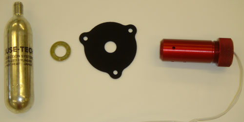
Above you can see the part among the other parts of the CD3 system it goes along with. (This one is cut in 0.063" Acrylic using a laser cutter at my local TechShop.) Note that a standard steel washer is used to produce the correct spacing, and I use the washer on the cartridge side so that the tapered neck of the cartridge bears against a hard surface.
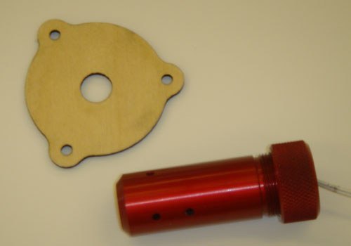
For actual use, I cut the mounting plates out of thin (0.128") plywood. Above you can see the part next to the CD3 body.
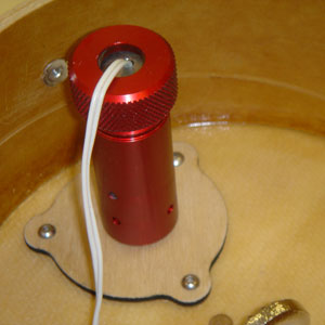
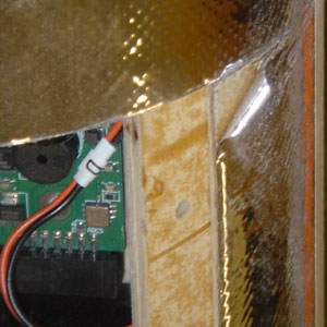
On the right you can see the CD3 unit installed in the forward end (carrier ejection) end of the new electronics bay.
The CO2 cartridge is recessed into the electronics bay body itself, with only the CD3 body exposed. The electric match wire is routed back into the electronics bay (into a separate compartment which contains the flight computers).
The advantage of the new Rouse-Tech mounting plates (for metal bulkheads) or my version (for plywood bulkheads) is that they require much less space than the original cylindrical casings and flanges. In my case, this allows me to mount three CD3 units in the same electronics bay (two for redundant main ejection and one for carrier ejection).
Building an M Carrier
Various M-class carriers have been made over the years, from the original set of 6 fancy carriers in 1999 made by Pius and I to the variety of creative designs made by individuals in later years. I needed to build some more carriers for 2008 and I decided to document the current design and actual building process.
Note that this design incorporates ideas from many people over the years. In particular, the removable partition idea is a great innovation, but I'm not sure to whom the credit belongs. This round of carriers was based on a drawing done previously, with only minor changes.
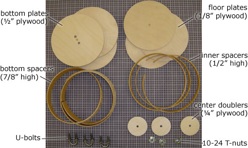
This first picture shows the parts laid out for the carrier, all but the body itself. (The body of the carrier is made from an 11 7/8" piece of phenolic coupler.) Note that I'm making three carriers at once.
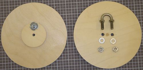
The first step is to build the two plate assemblies. The floor plate (left side) is made of very thin plywood, much too thin for the T-nut. This is the reason for the smaller diameter doubler of ¼" plywood. Once these the floor and doubler are bonded together, the T-nut can be hammered in.
The bottom plate (right side) has a U-bolt for attachment to the payload section of the rocket. (You can see how I filled in the original center hole with a ¼" dowel and drilled two holes for the U-bolt.) These nuts will not be accessible once the carrier is assembled so use a thread locker (like Loc-Tite® red).
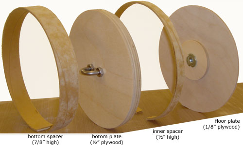
Here are all the pieces lined up ready to be bonded into the carrier body (not shown). The left side of the drawing is the bottom side, showing how the U-bolt will be exposed for attachment.
Finally assembly is easy: just bond all four parts into the bottom of the body (coupler tube) in the order shown above. If your bottom plate fits tightly, the easiest thing to do is insert it first, paint some epoxy on the inside wall above and below it, then install the bottom spacer from the bottom and the inner spacer and floor plate from the top.
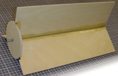
And finally, the purpose for the T-nut in the floor plate: the removable divider assembly. This is simply three pieces of 3/16" plywood bonded to a piece of aluminum #10 threaded rod. The threads make crevices to which the epoxy can bond, but be sure to clean the rod to remove machining oils first.