Punisher
In March 2015, David Reese of Wildman West proposed a drag race event for the June ROC-stock and I decided to join in. The motor was to be the CTI K1440 and the rocket a Wildman 3" Punisher kit.
The Pictures
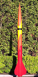
Painting was complete the weekend before ROC-stock. I decided to go for a colorful scheme, not following any particular design.
 |
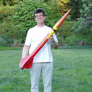 |
Above left is the "just painted" shot and above right is the "proud papa" shot. Ready just in time!
June 13 came and I made it into the playa and set up camp just in time to be the last one in for the drag race.
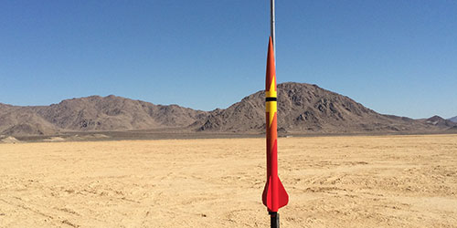
Above is my Punisher and below is the rack of all nine that were part of the race. (The second rail from the left is empty, mine is the second from right.)
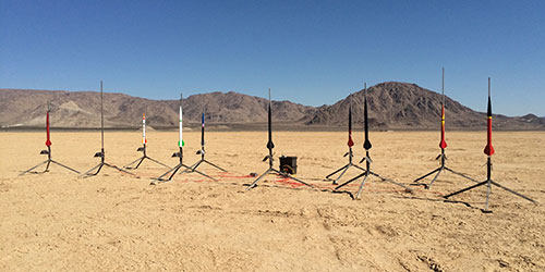
Shortly thereafter the rack was launched and up went the rockets, well not all went very far up...
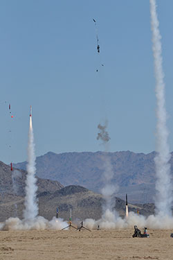
The shot above by Payton Kramer shows some rockets well on their way, some lifting off and two failing in flight. It turned out that three of the motors failed, including mine, due to a forward-end burn-through or blow-by.
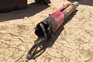
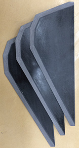
Above are the remains of my main airframe. You can see how the fiberglass tube was torched by the failed motor, causing the fiberglass tubing to actually unwind.
The Kit
The chosen rocket was a Wildman 3" Punisher kit and David held a sale for 10 kits to be used for the drag race. Mine arrived on April 15, 2015.
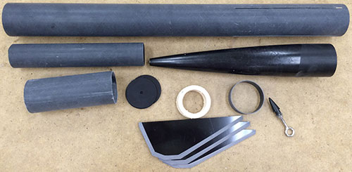
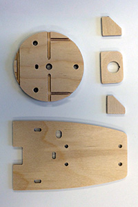
What you see above are the pieces that came with the kit. The tubing is thin-wall black fiberglass and the nose cone is molded in black plastic with what appears to be a phenolic tip. The fins are pre-beveled and the main airframe is pre-slotted.
This was my first Wildman kit (although I bought the tubes for my Iris from them), so I was a bit surprised at the low quality finish of the parts. Tube ends were unevenly cut, the centering rings had the wrong I.D. and O.D. and the surface of the nose cone was strangely mottled. I did appreciate the reduction in weight with the thinner fiberglass tubes however.
There were no instructions with the kit, but it appeared that the intention was for a dual-deployment arrangement with the nose body itself being the main recovery space. However, the fit between the coupler and the nose was way too tight for that to to be reliable, so I decided to use two parachutes in the main compartment and leave the space in the nose for a GPS tracker antenna. The intended motor (CTI K1440) is 22½" long, so recovery space was going to be tight.
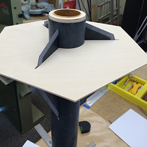
Since the centering rings were useless and I wanted to reduce aft weight, I went ahead and cut my own CRs and used a phenolic MMT instead. Since the K1440 also extends well forward of the MMT, it seemed prodent to avoid hardware in this area and bond an aramid strap directly to the MMT through a slot in the forward CR.
 |
 |
The three fiberglass fins where nicely beveled and all the same size, so that part of the construction went smoothly. I was also glad to see that the fin slots were perfectly spaced, and while a bit longer than necessary, they were nicely cut and a perfect fit width-wise.
 |
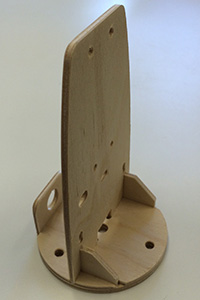 |
I decided to build the forward end pretty much as designed (other than not using the nose for main recovery). Above you can see the parts on the left and the dry-fit assembled elecronics bay for an Altus Metrum Telemetrum. (The open nose cone left plenty of room for the GPS antenna.)
 |
 |
Above you can see the components mounted to the electronics bay (LiPo battery in the back) and how it tucks into the forward end of the coupler, extending into the nose cavity.
Simulations of the flight suggested an apogee of 12,900' (3950m), so dual-deployment is important. I decided to use a Defy Gravity "tether" to keep the main parachute closed until the low-altitude point.
 |
 |
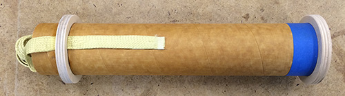
Above is a close-up view of the Tether and how the main parachute was bundled into a burrito, sealed with the tether.