Nike-Asp
During Summer 2000, Gary Rosenfield of AeroTech discovered some left-over motors built for a commercial customer of ISP (AeroTech's parent company). These motors were used to provide additional thrust for steerable fins on the Pegasus rocket, three motors per fin. The neatest thing about these motors are that they are end-burners which have a burn time over 20 seconds!
Gary suggested that this might be a good special purpose motor for AeroTech to produce and we decided to build a rocket or two to show them off at Balls X in September 2000. Ken Biba and I decided to build a rocket each and the Nike-Asp became my choice of design. Because of the low thrust, it would have been a waste to use this in a single-stage rocket. The rockets should use a booster stage to accelerate the Pegasus fin motor to Mach and get it out of the thicker air.
The rocket wasn't ready for BALLS 2000 and BALLS 2001 was cancelled due to September 11 so the full 2-stage configuration didn't fly until BALLS 2002.
The Pictures
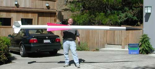
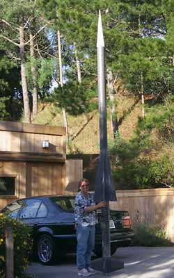
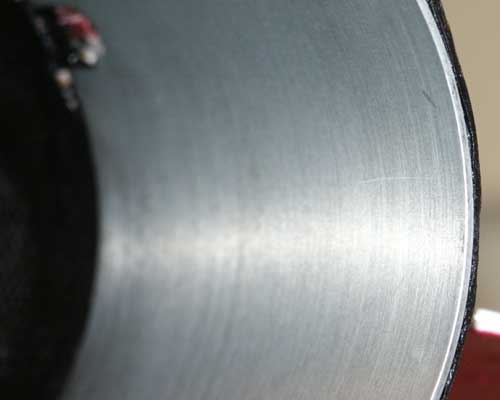
The picture above says it all: low weight.
(This is the 2-stage configuration which flew at BALLS 2002.)
Mudroc 2001
After the incredible amount of preparation (Sue and I had been working on this rocket since the previous summer), Mudroc finally rolled around on the fourth weekend of June 2001. The Nike-Asp was ready for its first two flights: the sustainer only (proving the light weight) and the two stage configuration with the baby-Nike booster (proving the strength).
Friday was the experimental launch day, which was the only day that we could fly the Sabre motors. So, the plan was two flights in one day. In order to be ready for all this, Sue and I prepped both stages on Thursday evening. Everything was laid out for the flights; only the sustainer would need to be re-prepped to fly the second time in the two-stage configuration. (Sue and I stayed up until almost 2:00am getting everything ready.)
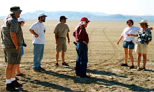
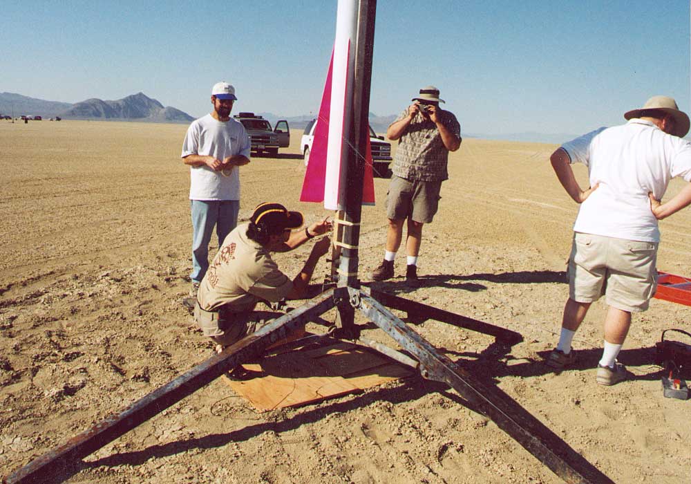
On Friday morning we went out to launch the rocket. We had lots of support. In the picture above, you can see the launch crew who came out to help. From left to right: Ken Adams, Mallory Geyer, Chet Geyer, Gary Rosenfield, Don Milhollan, Cara Rosenfield and Sue McMurray.
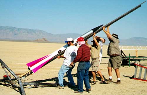
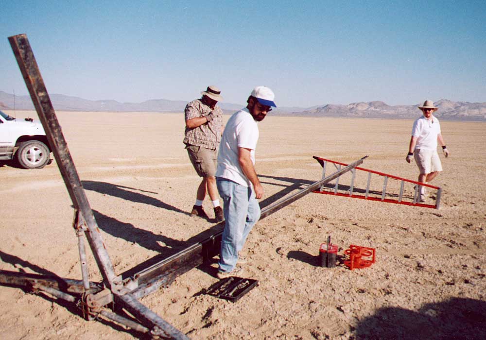
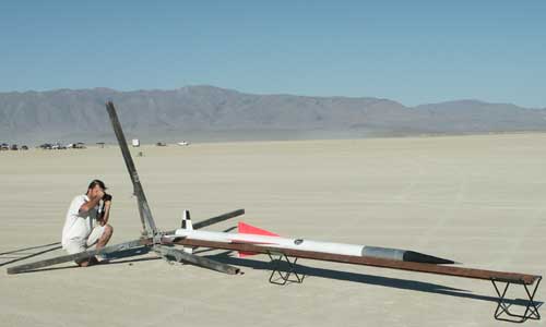
In its single stage configuration, the Asp was quite easy to load onto the rail. However, the rail itself weighs a ton and it took a bunch of people to lift it as you can see in the great picture above. (I'm in there behind Gary; picture by Sue.)
 |
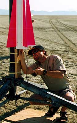 |
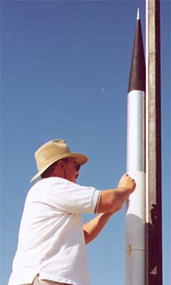
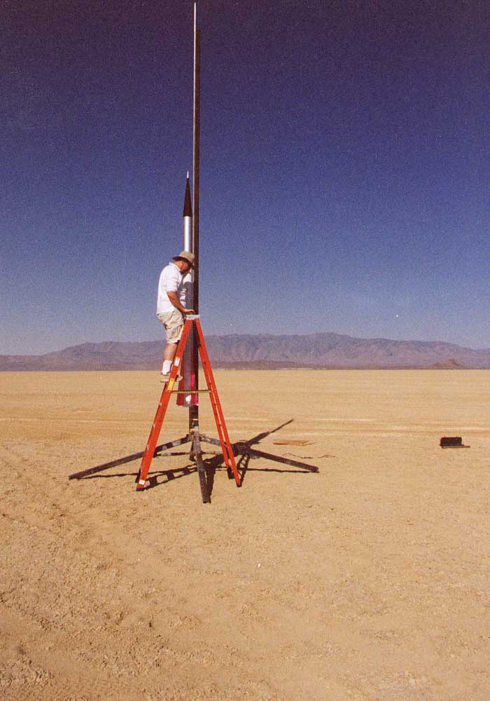
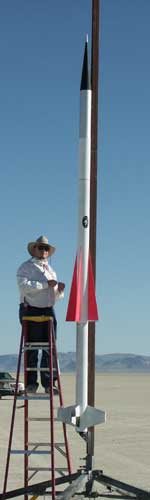
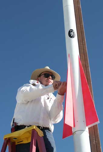
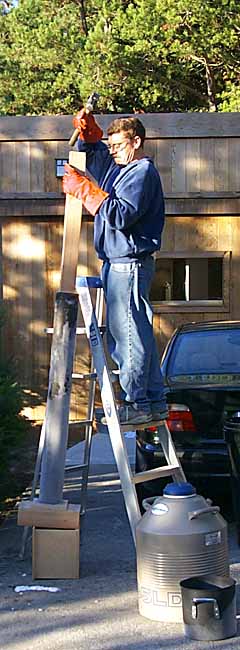
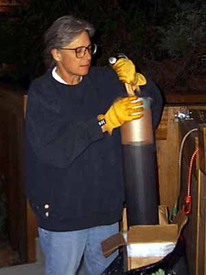
Once the rocket was upright, it was a simple matter to arm the dual G-Wiz units for recovery and the Adept for data only. Then we installed one of Chet's super igniters in the conventional HPR way. On the left you can see me on the ladder and on the right you can see Gary installing the igniter.
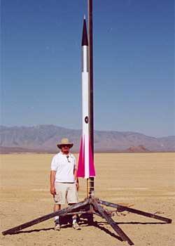
And of course here is the obligatory dumb rocket picture with me and the rocket. We should have had Sue in the picture too, but she was taking it. The rocket looks pretty small in the pictures with the whole 20 foot Unistrut rail, but in the picture with me, you can see how large it actually is.
It was a proud moment. This rocket represented a huge amount of work and a lot of learning and the flight would prove whether we had a revolutionary technique or a bunch of fragments.
Once the formalities at the pad were concluded,
it was time to head back to the flight line and launch the rocket.
(This was at about 9:00am.)
Here are some more photos of the rocket preparation, taken by Don Milhollan. (Click on them to see a larger version.)
|
|
|
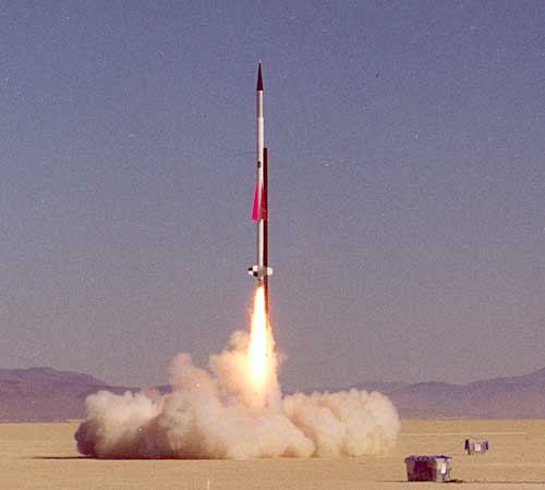
The rocket lifted off immediately and made a slow and stately ascent. There was very little smoke and flame as the motor is very efficient and the burn time was amazing! People oohed and aahed as the motor sound just kept on going and going.
In the picture above, you can see the rocket about a half second after liftoff. You can see some smoke from the flight, but very little. There was almost no wind at this point in the morning and the flight was very straight.
On recovery, the rocket appeared to be in perfect shape. There was no visible damage nor even any obvious cosmetic damage. The wind came up a bit by the time we actually flew at 9:00am, but not enough to drag the rocket along the ground. Everything had worked perfectly!
As we went back, we could hear the Adept ALTS82-50K beeping 24,424 feet. (This was amazingly close to the simulated altitude of 24,240 feet from RockSim.) The two G-Wiz units blinked out 24,497 and 24,733 feet.
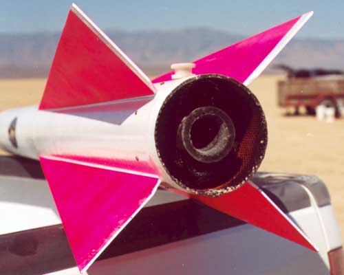
As we got back to camp, I noticed that the back end of the rocket had been damaged by heat. The end of the nozzle is just about flush with the aft end of the sustainer, but apparently base drag had pulled enough of the exhaust heat into the airframe to burn off the fiberglass and epoxy on the inside of the aft end. The carbon fiber was still there, but the epoxy was gone and the cloth was flexible again!
There would be no two stage flight at this launch since the sustainer couples to the interstage at this point. We decided that the sustainer would need to be repaired with an aluminum sleeve in the aft end to handle the heat.
Since it didn't go in the booster as planned, I decided to fly the Redline M2000 in my big Arreaux the next day (at the regular launch).
BALLS 2002
|
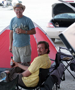
My brother Phillip and my friend Rodney came with me to the BALLS 2002 launch and we
had a great weekend.
Here you can see the two of them yucking it up outside my R.V. on Friday evening.
Neither of them are rocketeers, but they had a great time out at Black Rock Desert and enjoyed helping me prepare and launch the Al Gorilla and the Nike-Asp in 2-stage configuration (with the baby Nike booster). Phillip was visiting from Peru, where he is currently living. He had come up for my wedding on September 27. Rodney lives in N. California and had driven up to meet us on Thursday. |
|
The weekend was beautiful with almost no wind, even during the afternoons.
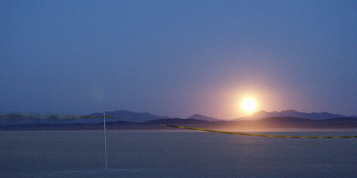
We had the most beautiful harvest moons, and it was full moon on Saturday night. (The picture above shows the moon on Saturday evening!)
On Saturday afternooon and evening, the three of us prepped the Nike-Asp. This two stage flight was one of the most complex single flights I've done. The baby Nike booster had a G-Wiz LC deluxe for a ½g separation charge (using the staging feature of the G-Wiz) and a main recovery charge.
The Asp sustainer had an Adept high-current stager for sustainer ignition. We used an 8 second delay from booster liftoff. (The M1939 booster motor burns for about 6s.) With about a second to light the sustainer motor, that creates a staging delay of about three seconds, which was the maximum I was willing to delay sustainer ignition. As it turned out, there was absolutely no wind on Sunday morning, so the delay was perfect. The sustainer motor was again the ISP Pegasus fin motor, a 20+ second end burner.
The Asp also had an electronics bay for recovery, using a G-Wiz LC Deluxe and (for my first time) a G-Wiz MC. The sustainer was set up for dual deployment with the usual "backwards ejection" or "anti-zipper" design with the drogue break in the center and the main break at the nose cone.
Finally about midnight on Saturday the rocket was prepped and ready for flight first thing Sunday morning.
Above you can see the Nike-Asp assembled on the rail and ready to be raised. Jason Evans came by to take a picture and so he made it into mine.
 |
 |
The pictures above, by Phillip Coker, give a better perspective of the size of the rocket (17 feet). On the left is me on the ladder, ready to arm the electronics. On the right is me arming the staging electronics, right above the motor.
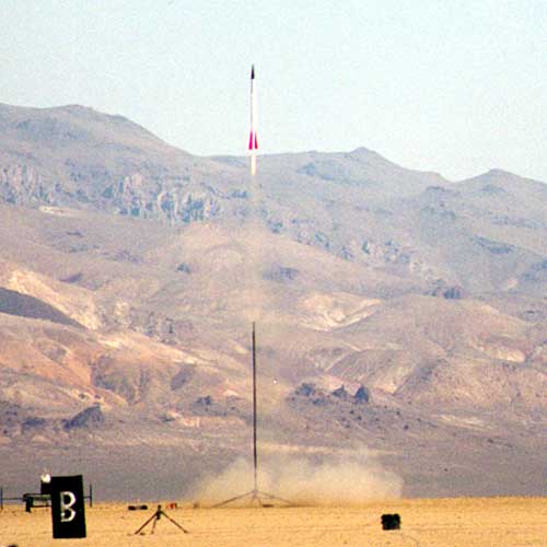
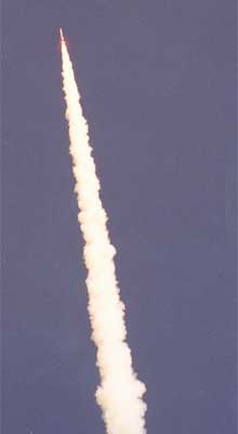
The weather was perfect: cool, no wind and not a cloud in the sky at about 9:00am on Sunday when we we ready to launch. Above you can see the Nike-Asp lift off on the booster M1939.
 |
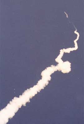 |
The pictures above show the booster thrust and just after staging. With no wind, the flight was completely straight. (I was almost directly underneath the flight, which causes the strange angles.) On the right, you can see the booster smoke blowing away, the wispy trail, then the smoke from the sustainer burn.
The sustainer flew to more than 40,000'; 39,863' according to the G-Wiz LC Deluxe and 39,809' according to the G-Wiz MC. Note that G-Wiz units truncate the altitude at 40,000' so you have to look at the barometric curve from the MC, which looks like the flight went to about 44,000'! (The booster apogee was 7,772' according to its G-Wiz LC Deluxe.) However, because of the thin air that high, the apogee charges did not generate enough force to open the rocket. The rocket came in ballistic to 1000' where the main parachute deployed. The high-speed deployment zippered the airframe down to the electronics bay and pulled the U-bolts out of the bulkheads! However, the electronics bay itself and both altimeters survived.
This flight is a personal altitude record for me; over 40,000' feet!
The graphic above is a screen capture (or rather four of them) from the G-Wiz Flight Viewer software. Click on the four non-grayed out tabs for different information on the rocket. (I'm not sure why the altitude graph is truncated; presumably it's a bug.)
The Design
I decided to model the Nike-Asp at 81% because that results in a minimum diameter sustainer for the 5" O.D. Pegasus fin motor. This makes a very large rocket, with the Nike booster being 13½" in diameter and 10 feet long and the Asp sustainer being 11¼ feet long! Sue McMurray agreed to help me with the fabrication of the parts and her experience with composites was invaluable. We have built the lightest, strongest and stiffest rocket I have seen yet. Thanks Sue!
The only bit of sense Sue and Gary were able to talk into me was to build a smaller booster first and save the 6-motor monstrosity for a later date. This turned out to be a very good choice as time started to fly by once we got to work. (The larger Nike booster never did get built.) I decided to do a "baby Nike" booster based on the same 5" tubing as the Asp sustainer. The "baby Nike" isn't really scale, although it is in rough proportion. This also gave me an opportunity to build up the Nike profile fins in a smaller prototype.
Here are diagrams for:
- Asp sustainer airframe
- Baby Nike booster airframe
- Three sets of fins
- Asp nose cone
- Nike booster centering ring
- Asp sustainer bulkhead/ring
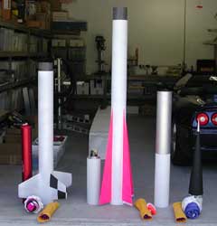
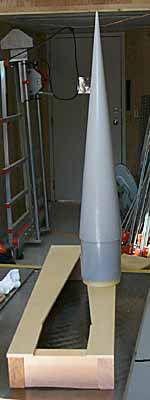
On the right you can see the baby Nike-Asp assembled for the first time after the bulk of construction was completed. Even with the baby booster, it's an impressive rocket! All that pretty carbon fiber is about to be covered in paint.
This configuration will fly at the AERO-PAC Mudrock launch in June 2001. This picture was taken in early May so things are progressing nicely at this point. However, there are plenty of details still to be done, certainly enough to create a rush just before the launch.
How well did we succeed at keeping the rocket light? Well, the ASP sustainer, despite being built to withstand mach flight, weighs less than 9¼ pounds. That's a 11¼' (135") long 5¼" diameter rocket set up for dual deployment and heavily reinforced with carbon fiber!
| Component | Weight # |
|---|---|
| Baby Nike booster | |
| booster airframe | 5.64 |
| booster recovery | 2.06 |
| motor at burnout¹ | 7.51 |
| 81% Asp sustainer | |
| Asp booster | 5.90 |
| Asp payload | 2.10 |
| Asp nose cone | 1.22 |
| Asp recovery | 4.08 |
| motor at burnout² | 7.28 |
² The sustainer motor is the ISP Pegasus fin motor. The burnout weight was measured directly.
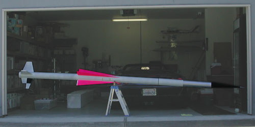
On May 28, 2001 (Memorial Day Monday), I had the sections painted, weights measured and recovery system chosen. The last thing is to determine the dry C.G. of the rocket and below you can see the rocket balanced at the C.G. point with both stages. (I like to override the mass and C.G. in RockSim to make the simulations more accurate.)
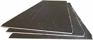
Airframe Tubing
The airframe would be completely scratch built from honeycomb composite. This material is a flexible sheet which looks somewhat like the inside of a corrugated box with diamond shaped cells. Once inside and outside layers are laminated to the honeycomb, the structure becomes very strong and stiff, especially for its weight. You can also choose whatever lamination is necessary to produce the desired strength and stiffness characteristics.
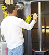
In order to build the 5" I.D. sustainer airframe sections, I had a mandrel produced. This was a 5.030" O.D. aluminum tube with a polished surface. A mandrel needs to be very smooth and of a consistent diameter so that the part can be pulled off it.
The mandrel also needs careful preparation before each use. A special mold release wax is applied, allowed to dry and buffed off three times to seal any remaining pores in the metal. Then, a liquid release film is sprayed into the mandrel in three coats. This liquid dries to a thin film which provides a buffer between the waxed mandrel and the part. Because it is a liquid and is sprayed on, it can conform to complex shapes that release cloth cannot.
To build the 13.5" O.D. booster airframe, I also needed a mandrel. However, because an aluminum mandrel would have been prohibitively expensive (not to mention hard to store), I decided to use a foam core which could be melted away after the tube was laminated. It turns out that Styrofoam shapes can easily be made locally, which meant that I could have the part made for me in three days.
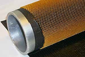
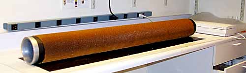
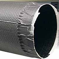
The 5" airframe sections are made with 4oz. fiberglass cloth, 5.7oz. carbon fiber and honeycomb core. On the right you can see the end of the mandrel with the three inner layers applied: fiberglass, bidirectional carbon fiber cloth and the honeycomb core. All three were applied in the first layup. Below you can see the whole tube (50" mandrel to make 48" tubes) ready for the outer layers to be applied (unidirectional carbon fiber and fiberglass).
 We used my trusty FoodSaver® to bag the airframes since it works so nicely with tubes.
(For more on the techniques, see my
kitchen table vacuum bagging article.)
We used my trusty FoodSaver® to bag the airframes since it works so nicely with tubes.
(For more on the techniques, see my
kitchen table vacuum bagging article.)
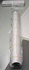
On the right you can see the first tube in the bag with the outer layers (5.7oz. unidirectional carbon fiber and 4oz. fiberglass) applied. This is always a very satisfying stage to get to as the hardest (or at least the most painstaking) part is all done at this point. (Or so we thought!)
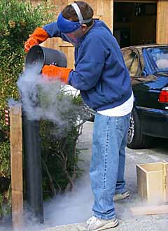
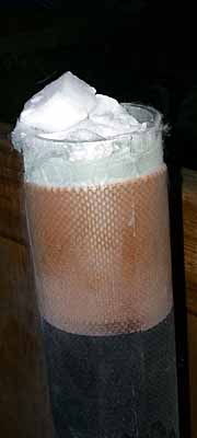
Releasing the part from the mandrel turned out to be quite a challenge. The idea we had was to shrink the aluminum mandrel with cold. (Aluminum has a very high coefficient of thermal expansion, which was why I chose it for the mandrel material.) Our first try was packing the inside of the mandrel with dry ice (frozen CO2), but this wasn't quite enough to release it.
After some time building wooden jigs and pounding on the mandrel and part, we decided to bring out the big guns: liquid nitrogen. At 77° Kelvin, that should be cold enough! LN is quite easy to find because it is used so frequently as a cryogen. After finding a local place, Sue picked up a 35 liter dewar and we went to town. The dry ice soak and the liquid nitrogen shock did their work and we were able to pound the mandrel out of the part.
 |
 |
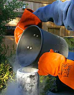 |
The pictures above show the process. At the top left, you can see the mandrel in a wooden base with a hole cut just the right size for the mandrel to fall inside, but the tube to but against the flat surface. At the bottom left, you can see a closeup of me pouring the liquid nitrogen into the mandrel trying to get it a uniform temperature (very cold). On the right is the start of pounding the mandrel out of the tube. We used a flat disk which pushed on the end of the mandrel inside the tube to pound on and the mandrel was able to slide through the hole in the base. Not shown are the several hours of letting the tube cool, packed inside and out in dry ice.
On the left you can see the end of the first tube pulled from the mandrel. Note the crease on the near side near the top from the vacuum bag. This is an annoyance that we managed to reduce significantly by using a second FoodSaver bag inside the bag on which we drew the vacuum. Where the edges of the bag pinch the layup, a ridge is created full length along both sides.
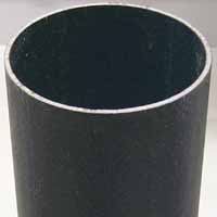
But, all in all, the tubes came off the mandrel perfect. The motor fits properly and the inside is very smooth. Truly a beautiful piece of work, if I say so myself. On the right you can see the end of the tube cut straight and with the honeycomb ends filled with epoxy and sanded.
This took a huge amount of effort, but we have a piece of the lightest and strongest possible airframe, in the perfect size. The 41½" payload section weighs 565.5g, which is only 163 grams per foot! (Compare that to 258g/ft for unreinforced 6" phenolic tubing and 146g/ft for 3.9" tubing.)
The first two tubes we made used unidirectional carbon fiber inside and outside, with the fibers run longitudinally. We found out that this didn't given enough hoop strength when it came time to fill the gap left by sanding out the wrinkles on each side. We applied a strip of fiberglass over the gap and put it into the bag. A few minutes later, we heard a loud pop and a crunch and the pressure had flattened the tube!
At that point, we realized that we needed to use bidirectional carbon on the inside of the tube to give it strength in both directions. The second tube had already been laid up with unidirectional, but that was OK because it made good couplers which we could reinforce inside with bidirectional carbon cloth. To make the couplers, I cut the tubing to appropriate lengths and then cut a chunk out the amount necessary for the reduced diameter. We then bonded edges of the coupler and inserted it into regular tubing, then laid up bidirectional cloth inside the coupler.
Another thing we learned was how to get rid of the wrinkles. I'd known this before, but forgot when we did the first tube: only do one layer of reinforcement at a time! Doing two will generally cause nasty wrinkles, whereas if you do them separately the cloth will be tighter and wrinkle less. Another trick is to use two vacuum bags with the seams oriented at 90° angles. The inner bag isn't vacuum bagged on, just taped as tightly around the part as possible. Then the whole thing goes into the "real" outer bag and is vacuumed. The rest of our tubes came out without the seam wrinkle at all!
 |
 |
I also learned that the liquid nitrogen wasn't necessary, as Sue had known all along, even though it was fun to play with. We started using more dry ice and soaking the mandrel for longer and got to the point where we would tap the end of the mandrel and it would drop right out. Partly this was that the mandrel became "seasoned" and partly it was the long cold soaking in dry ice (12 hours or more). In the picture above left you can see Sue packing dry ice into and around the mandrel. Above right you can see the mandrel is filled up with dry ice inside. It's also inside a box and more dry ice is packed around the outside. You can also see that we're doing this in the middle of the night. Things got quite hectic making all these parts and we put in more than one all-nighter.
Fins
Rather than make the fins out of G-10 or plywood, I decided to lay the fins up using Balsa cores sandwiched with carbon fiber. This construction results in a much lighter fin than G-10 and a much thinner and lighter fin than plywood. Plus, the fins are very stiff because of the carbon fiber used in the construction, which is important for rockets flying Mach.
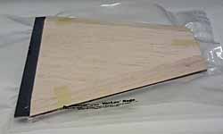
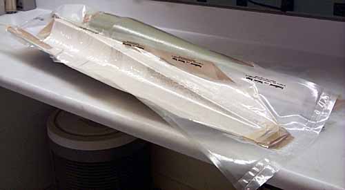
The Asp fins are a simple layup of carbon fiber on a 1/16" balsa core. (We used 5.7oz. unidirectional carbon fiber for the fins as well as the airframe tubes and bulkheads.) Laying up flat fins like this is quite easy and you can apply all layers at the same time since the whole thing is vacuum bagged flat.
On the right you can see two of the four Asp fins in the bag. I used a small vacuum bag setup for wood veneering. (Wood working is another of my many hobbies.) This system uses a venturi to pull a vacuum and automatically maintains the vacuum between 20 and 25inHg. This is an excellent system for bagging parts with at least one flat surface.
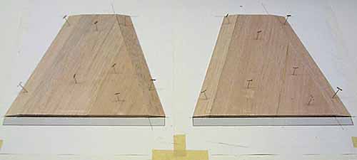
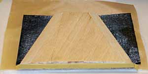
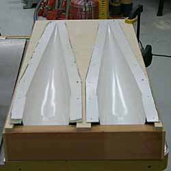
For the Nike fins, we first made core sandwiches of 1/16" balsa sheet and carbon fiber, run from fin root to fin tip. Below, on the left, you can see a diagram of the layers. Balsa is shown in yellow and carbon fiber in black. The arrows show the direction of the fibers and balsa grain. (The inner carbon layers go from root to tip and the outer layers go parallel to the root.) On the right you can see the cores (three of the four) after they were cut to size.
 |
 |
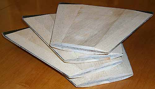
To create the thick Nike fin profile, we built up eight profiles from balsa. I found the balsa angle which the closest to correct profile for the leading and trailing fin edges. (They are actually a compound taper.) I printed out templates for the profiles and we built them on a building board, using R/C airplane construction techniques.
Once these were glued up using white glue, we epoxied them onto the cores already cut
to shape and clamped them to the cores by vacuum bagging.
(Using the FoodSaver® again.)
 On the right you can see one fin with the rough profiles applied in the FoodSaver bag.
Note that the center of the fin profiles are ¼" thick with the leading and trailing edges made with airplane trailing edge wedges 1" wide. Balsa in many shapes is widely available. It is mostly using by R/C airplane modelers and you should be able to find it in the R/C construction supplies section of your hobby shop. Balsa is very light and easy to work, which makes it ideal for many purposes. It also absorbs epoxy well and is dense enough not to deform during vacuum bagging.
Once the profiles had cured fully onto the core pieces, it was time to do the final shaping. Nike fins have a compound taper, with the taper wider at the root edge of the fin than at the tip. The angles I chose made an appropriate taper at the tip, but an increasing taper needed to be sanded towards the fin root. I marked out the lines on the face of the balsa and we sanded down the correct profile. This was a lot of work, but at least I was able to use a disk sander to remove the bulk of the excess balsa.
Next, it was time to laminate the outer layer of carbon fiber. This time, we ran the fibers parallel to the root, 90° from the inner carbon fiber.
 A single layer of carbon fiber was laminated onto each side of the shaped fin and back they
went into the vacuum bag.
We didn't apply the fiberglass veil at this time because that was applied after the fins
were bonded to the airframe, using a single piece from one fin tip, over the airframe
and up to the adjacent fin tip.
This makes a continuous skin on the outside of the airframe/fin which provides good strength
and a smooth transition.
A single layer of carbon fiber was laminated onto each side of the shaped fin and back they
went into the vacuum bag.
We didn't apply the fiberglass veil at this time because that was applied after the fins
were bonded to the airframe, using a single piece from one fin tip, over the airframe
and up to the adjacent fin tip.
This makes a continuous skin on the outside of the airframe/fin which provides good strength
and a smooth transition.
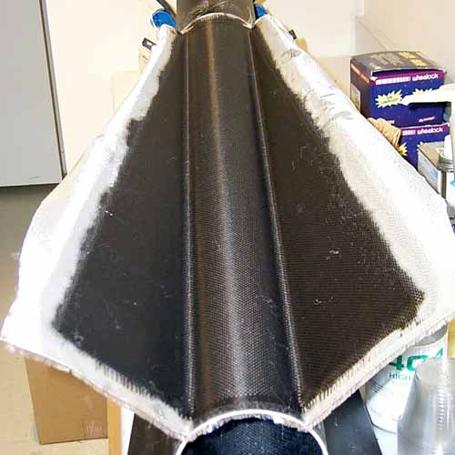
Above you can see one of the Asp sustainer fin bays after the reinforcement has partially cured to the "leather stage." At this point, the excess was cut off with a hobby knife and then allowed to fully cure. Each bay was reinforced like this with two layers of 6oz. carbon fiber followed by one layer of 4oz. fiberglass. See the article on the Tip-to-tip Jig for full details.
Bulkheads
The bulkheads too were made out of composite layups with balsa cores. To make ½" bulkheads I used ¼" balsa and various composite layers (see the illustration on the right). From the top down, the layers are:
- 4oz. fiberglass cloth
- carbon fiber cloth
- ¼" balsa
- carbon fiber
- ¼" balsa
- cloth made with Kevlar®*
- fiberglass
The grain in the two balsa layers are oriented 90° to either other as are the fibers in the two carbon fiber layers.
The reinforcement with Kevlar® fibers provides good mechanical strength for attaching U-bolts and that side will be used for the back side of any such hardware attachments.
Like the Asp fins, the bulkheads were laid up with all layers at the same time and bagged using the veneer press vacuum bag. This produced an incredibly strong yet very light bulkhead with just the right mechanical properties.
Nose Cone
The Asp nose cone is actually a true cone, which makes it easier to specify and easier to turn. (See the nose cone drawing.) In order to keep weight down, I decided to make a fiberglass nose cone. Of course, this means making my own mold.
FibreGlast make a great set of instructional videos for hobbyists and their video A Step-by-Step Guide to Molding Fiberglass got me started. It's a lot of work, but after watching the video I had the confidence to give it a try.
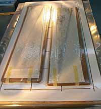
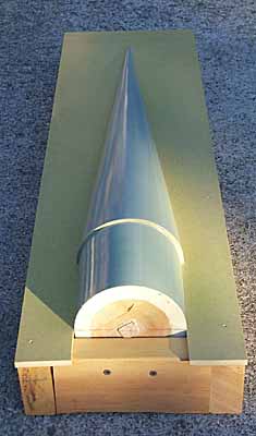
The first step is make a plug, which is a turning of the exact shape of the finished nose cone. I had a local craftsman (San Francisco Wood Turning) turn a nose cone out of maple to the proper size for the tubing and the proper length. The next step was to make a board into which the plug would sit, half submerged. This allows the first half of the mold to be formed around half the plug and with a lip formed on the board.
Below left, you can see the plug primed and sanded and the board with a plug-shaped cutout. Below right, you can see the plug installed in the board, the edges sealed with clay and waxed and painted with mold release.
 |
 |
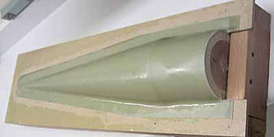
On top of the plug and base, the first mold half was then formed using hand fiberglass layups. The mold should be three times as thick as the part to be pulled from it. Since the nose cone was to be made of 4oz. fiberglass, 5.7oz. carbon fiber and 6oz. 'glass layers, this meant three layers of 4oz. 'glass and nine layers of 6oz. Below you can see the first half of the mold laid up. Note that the excess past the lip and on the end has been trimmed off.
Once the first half of the mold is fully cured, the half mold and part (still attached together) are removed from the base. The plug and first half are cleaned up and more wax and mold release are applied. Then, the second half can be laid up in just the same way as the first.
Laying up the second half went more quickly as we already had the reinforcement cut from doing the first half. Once the second half had cured, it was time to remove the plug from the mold and clean the mold halves. Releasing the plug from the mold halves wasn't too hard. (The FibreGlast video made us think it was going to be a chore.)
Once the mold halves are done, the plug is set aside (we're done with it now) and the halves are thoroughly cleaned and dried. Then, just as with the plug, three coats of wax were rubbed on followed by three light coats of sprayed PVA. On the right you can see the two halves laid out after waxing.
Finally, the mold was prepared for making the actual nose cone! A gel coat with white pigment, then two layers of 4oz. fiberglass and two layers of 6oz. 'glass were applied. In addition, the shoulder had one layer of unidirectional carbon fiber. In order to keep all layers tight and remove excess resin, we did something in addition to the FibreGlast instructions; we vacuum bagged the halves. Below you can see the two half cone layups in the mold halves under vacuum. Another use for the trusty FoodSaver!
Once the half cones had partially cured (reached a "leather" consistency), the vacuum bags were removed and excess fiberglass was trimmed away, leaving the cone halves even with the edges of the mold halves. We then applied thickened epoxy along the edge at the tip (where it would be too hard to reach once the halves were together.
Now the halves were joined. Below you can see the mold halves held together with special spring pins (and two clamps when we ran out of pins).
More thickened epoxy was applied all along the seam from the inside, followed by a piece of fiberglass tape along each side of the seam. We also applied another layer of unidirectional carbon fiber, oriented 90° to the first, and another layer of 6oz. 'glass in the shoulder. Finally, release and breather were applied inside the shoulder and squeezed into the part with a balloon. Above you can see the balloon in the end, all ready for curing. Sue did the actual layup of the part in one marathon session, as is necessary with this technique.
Once the mold halves had cured over night, we removed the balloon, release and breather and released the part. Again, this turned out to be pretty easy and everything came apart with no problem.
The first thing is to cut off the mold line flash and scrub the nose cone with warm water to remove the PVA. And it is a wonderful thing now that it's done! On the right you can see the nose cone standing up next to the plug.
The shoulder of the nose cone turned out to be too large for the tubing. We noticed that the wooden plug had split where the wood blanks were glued up for turning and believe that the wood plug expanded when it soaked up water during wet sanding the surface. At any rate, it took a bunch of sanding to get the shoulder to the right size for the tubing. You can see the fiberglass and carbon fiber showing through where the white gel coat has been sanded away. We had two layers of gel coat, so luckily we didn't have to sand into the reinforcement.
Phew! That was a lot of work. However, the resulting part makes it all seem worthwhile. We have a perfect scale nose cone, very light and very strong. And finished just in time to take to Balls and show off (even if the whole rocket isn't ready to fly yet).
In thinking over this process (this nose cone was my first attempt at molding fiberglass), several things came out. First, use a plug which is dimensionally stable. Wood absorbs water and glued-up blanks joints can crack. Solid plastic or aluminum would make a better plug, although they would be more expensive. However, it would also be possible to maintain finer tolerances than is possible with wood.
Another thing is that we had some chipping at the base of the cone, where it turns inward to the smaller shoulder diameter. This was because there were air bubbles under the fiberglass and because the filler material was too soft. In the future, I will use epoxy thickened with colloidal silica and take care to work it into all corners before applying fiberglass. However, these bubbles were easily filled after the shoulder was sanded.
Asp Repair
As reported in the Mudroc launch report above, the inside aft end of the Asp was burned away by the heat from the Sabre motor. To repair this properly, I clearly needed a better solution which would withstand the heat which developed at the base of the rocket.
After consultation with Chet and Sue, I decided to use an aluminum sleeve, bonded in place with high-temperature epoxy. Shadow Composites sells a good general purpose bonding epoxy which can withstand higher temperatures than average (400-500°F).
The walls of the airframe (Nomex honeycomb plus inside skin) are about 1/8" thick so the heat shield sleeve would be 1/16" thick leaving room for 1/16 of insulating adhesive. Plus, the composite motor retainer that I'd built had turned brittle from the heat so I had one machined from aluminum. (Download the sleeve drawing and the retainer drawing.)
After the sleeve was bonded in place, the aft end had a perfect smooth and consistent surface. Also, a surface which would survive the heat from the motor.
Historical Info.
Text and pictures from Rockets of the World.
While NACA flew its Nike-Cajuns, the Naval Research Laboratory (NRL) used Nikes to boost the Navy's favored Deacon replacement, the Asp. Cooper Development created the Nike-Asp, a staged combination along the lines of the Nike-Deacon and Nike-Cajun. Most notably, the Nike-Asp (or ASPAN for Asp And Nike) carried NRL payloads for studies of the sun in X-rays and ultraviolet light during the International Geophysical Year (IGY).
One series of launches involving Nike-Deacons and Nike-Asps took place from San Nicolas Island, California.
Researchers maintained contact with solar astronomers at Mount Wilson observatory, and would launch a vehicle at the first hint of a solar flare. This operation exhausted the NRL's funds for the IGY.
There was one other project NRL scientist Herbert Friedman had coveted: a shipboard launch of half a dozen Nike-Asp rockets during a total eclipse of the sun. There was no money for such an adventure, but on October 4, 1957, the Soviet Union launched Sputnik 1. Space was now a national priority. So the Navy sent the NRL's rocket scientists off on a South Pacific adventure.
The USS Point Defiance was selected to carry eight Nike-Asps to the vicinity of the Danger Islands in the South Pacific. It reached the appointed spot seven weeks in advance to allow traditional astronomers time to assemble an observatory on Puka Puka Island. While the Navy construction team worked on shore, the NRL rocket group fired off two preliminary launches to collect X-ray fluxes from the uneclipsed sun. The American team passed the evenings watching movies, inviting the native islanders to join them. The islanders quickly picked up the subtleties of American culture, Hollywood style. Even the rocket crews were affected by a movie overdose, painting their missile charges with cinematic names and phrases.
On October 12, 1958, the moon's shadow crossed Puka Puka Island. But unbroken clouds hung over the island, leaving the ground-based astronomers with nothing but memories of islanders and movies. 'Me skies were fine over the Point Defiance, but the rocket crew faced troubles closer to Earth.
Six rockets, each bearing at least one nickname, were spaced 20 feet apart on launchers on the deck. The NRL team figured that one Nike booster, releasing the energy of a half ton bomb as it roared from the deck, would probably not damage its neighbors or trigger an explosion that would sink the ship.
As the moon began to cover the sun, the firings began. The blast of the first rocket chased curious sailors to safer comers of the ship, and sent its payload successfully above Earth's X-ray opaque atmosphere.
The second rocket bore the name Tondelayo, a Hollywood South Seas temptress, scrawled in red paint. Ten minutes after the first launch, Tondelayo was on her way to a successful sun-gazing mission. Two more rockets took off in the next ten minutes as the sky darkened. But when the firing button was pressed for the fifth rocket, nothing happened.
Don Brousseau, the NRL team's electronics expert guessed the igniter umbilical had shaken loose in the controlled explosions of the preceeding launches. He clambered up the launch tower, past a fin bearing the nickname of this round, "Miss Fire." After giving the connector a good shove, he ran to the relative safety of the nearest gun tub. Again the firing button was pressed. Again nothing happened.
The Moon would not wait, and Friedman decided to fire the next round. Again, there was no fire. Brousseau scurried across the deck, repeating the connector fix on rocket number 6, Rose Mary. Finally, 38 minutes after the first launch, Rose Mary rose off the deck, carrying its hopeful message into space, "Take Me to Your Leader." Alas, Rose Mary fell short, due to a failure during her second stage burn.
Analysis of the data from the four good flights showed that most of the sun's X-rays came from active regions that were successively obscured by the moon during the eclipse. But there was also considerable X-ray flux during totality. The solar corona, the tenuous outer atmosphere of the sun, was the source. This discovery showed that the sun's corona was hotter than the surface of the sun itself. The observation of X-ray hot-spots opened a whole field of solar X-ray imaging. Years later, Skylab regularly photographed the sun in X-rays. To this day, sounding rockets are using improved X-ray telescopes to observe the solar corona in unprecedented detail.
Even Miss Fire had a chance to do some science. After a thorough check-out, she flew from the deck of the Point Defiance the next morning. This flight was to collect background data. But by sheer luck, Miss Fire reached apogee just at the peak of a major solar flare, sending back the best flare data to date.
When NASA was created in 1959, the NRL rocket group transferred to the new agency. The old Navy hands continued to order Nike-Asps from Cooper Development. One notable experiment was NASA flight 3.13 launched on August 17 of that year. At 5:18 AM, the rocket took off from Wallops.
At an altitude of 50 miles (80 km), it began trailing a cloud of sodium vapor. The cloud traced the flight of the coasting Asp to an altitude of 150 miles (240 km). The trail glowed yellow in the dawn sky while ground stations tracked the wind-blown trail. NASA scientists were delighted by the upper wind data. But they were not the only observers. The sodium trail was visible from as far as 700 miles (1,100 km) away, and that morning UFO reports poured in from as far away as Florida, Pennsylvania and Ohio. Since then, NASA has conscientiously informed the press about such ventures in advance.
Although the Nike Asp had a performance advantage over the Nike Cajun, it was less reliable. NASA flew fewer than 30 Nike Asps before abandoning the configuration in favor of the Nike Cajun and Nike-Apache 1963.
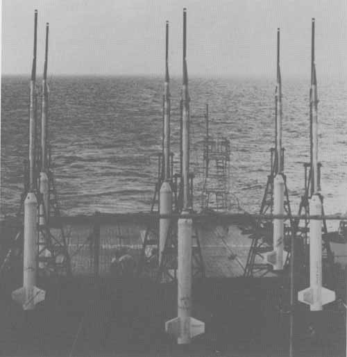
A half dozen Nike-Asps on the deck of the USS Point Defiance in preparation for a total solar eclipse.
* KEVLAR® is a trademark of E.I. du Pont de Nemours and Company.