Minie-Magg
My wife Renée wanted to take part in building a rocket. She has natural talent and training in drawing and painting so I decided to build a rocket for her to finish. She picked out the Loc/Precision Minie-Magg rocket as one she liked the look of and I started building it.
In 2016 we moved and all projects that had been sitting for more than five years without progress were abandoned. This one one of them.
The Pictures
The Kit
The Minie-Magg kit is one of those short, fat rockets with a 5.5" diameter tube and an overall length of only 37". The kit comes with a single piece of body tube, slotted for the fins. The fins are 3/16" plywood with through-the-wall tabs (but not all the way to the MMT). It's your basic Loc/Precision kit.
Of course, I immediately threw away the recovery system components. The next thing to do is figure out how I would build it. It seems silly to build it as designed with a single 38mm motor mount tube so I planned to put in a 16" long 54mm MMT instead. That still leaves a lot of space unused and we can't have that! So, I decided to put a cluster of six 8" long 29mm motor mount tubes in as well. Why not make this a cluster/air-start rocket?
 |
 |
|
 |
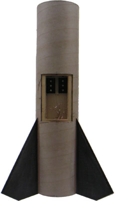
Above you can see the rocket after my modifications. The body is covered with a layer of 4oz fiberglass, the fins are reinforced with 6oz carbon fiber, the core has been replaced with 7 MMTs and an electronics bay has been added.
The Core
I wanted to keep the same overall dimensions as the kit so that meant designing an electronics bay into the existing shape. The 16" long central 54mm MMT became the spine of the rocket and the guts of the rocket are built around it.
Above you can see the 16" long 54mm MMT marked to show the organization of the rocket. The left-side mark is the top of the forward CR. The center mark is the top of the middle CR, separating the 29mm MMT section from the electronics bay. The right-side mark is the bottom of the aft CR.
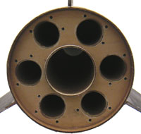
Above you can see the two custom centering rings, with the six 29mm MMTs around the central 54mm hole. Note how the holes don't go all the way through the middle CR (on the left).
 The aft CR then got three holes for each motor with a 4-40 T-nut in each.
One of the T-nuts is for motor retention and the other two are for ignition wires which
run up into the electronics bay.
The aft CR then got three holes for each motor with a 4-40 T-nut in each.
One of the T-nuts is for motor retention and the other two are for ignition wires which
run up into the electronics bay.
To the left, you can see the six leads soldered to the pairs of T-nuts for each of the motors. This will allow me to run many combinations of clustering and air starting the 29mm motors around the outside.
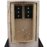
The electronics bay has space to accomodate an Adepts ALTS25 altimeter and a ST236 dual channel high-current stager. (These two units have the same layout with four mounting holes in the corners.)
Like many Adept units, these are powered by 12v lighter batteries. However, the stager also accomodates an external battery to provide more current for powering the outputs.
On the left, you can see the electronics board that mounts between the middle and forward CRs and provides space for main recovery and air-starting. (There are 2-56 T-nuts in each corner of the unit mounting locations since there will be no access from the back of the board.)
At the top are two 9v battery holders. One or two 9v batteries will be used to provide more current for lighting the air starts than the 9v lighter batteries are capable of. (Only one is requried, but I provided two holders so that I can run two batteries in parallel if paranoia sets in.)
 Once all the components were ready, the core was assembled.
First the center CR was put in place on the central MMT and tacked with CyA.
Next, the six 29mm MMTs and the aft CR were tacked in place.
Lastly, the electronics board and forward CR were added.
Once all the components were ready, the core was assembled.
First the center CR was put in place on the central MMT and tacked with CyA.
Next, the six 29mm MMTs and the aft CR were tacked in place.
Lastly, the electronics board and forward CR were added.
On the left is the core, assembled and tacked together with CyA in preparation for final bonding with epoxy.
Note that all six leads for the 29mm motors are gathered together and come into the electronics bay from underneath. This allows many conbinations of air-starts, although the most likely configuration would be in two sets of three (because of the two output channels of the ST236).
There is also a small hole in the forward CR for the ejection charge for main recovery. Not visible is an eye bolt in the forward CR for recovery system attachment.
This whole assembly was then solidly bonded with epoxy, while everything was easily visible, before being installed into the airframe tube. (The fins are surface mount so can be mounted afterwards without the completed core interfering.)
Main Airframe
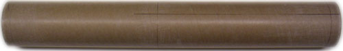
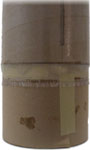
I used the body tube that came with the kit in pretty much the original configuration. (The tube is a Loc/Precision cardboard tube 24" long with three fin slots already cut.) I cut a hatch in the side to match the electronics bay area (shown above) and reinforced the cardboard with a skin of 4oz fiberglass.
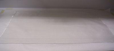
By now a very familiar procedure, the 24" long tube was very easy to reinforce. Since this tube is open at both ends, I put scraps of coupler in both ends for handles and covered them with masking paper. This allowed me to run the fiberglass past the ends of the tubes.
 |
 |
|
 |
 |
|
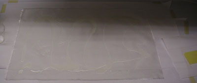
Above you can see the proces. At the top left, the fiberglass is laid out and ready and at the bottom left the epoxy has been poured on. (It doesn't take much; less than 2oz. for this 18" x 26" piece.) On the right, at the top, is the airframe after the reinforcement has been rolled onto the tube and on the bottom is the aft end of the tube showing the fiberglass extending past the end of the tube.
The Nose
Of course, short rockets like this aren't naturally very stable. On top of that, I've dramatically increased the weight at the rear with all the extra structure. And, if I use those MMTs, that will add even more weight in the aft.
I wanted to leave the normal kit appearance, which ruled out increasing the fin area. So, that left nose weight to improve stability. I started out by bonding a pound of led shot into the tip of the nose cone. This fixed weight could then be added to by bolting in additional weight as needed.
Those of you who have tried to epoxy plastic know that it doesn't make a very secure bond. I couldn't have the weight come loose and fall to the bottom of the nose cone during ascent so I used mechanical reinforcement as well as epoxy.
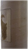
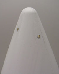
Before the epoxy and lead shot were poured in, two brass rods were inserted through the tip of the nose at right angles. (An eye bolt was located at the crossing point inside for additional weight attachment.)
To the right you can see the tip of the nose cone after the epoxy had cured and the brass rods were cut flush with the outside of the plastic nose. Once the nose is finished, you won't even know the reinforcement was there.
Fins
 I decided to use the kit fins.
They have a notch at the bottom that fits into a slot in the airframe,
but aren't really TTW since they don't reach the MMT.
(Well, I guess they are "through the wall," but not what most people mean.)
I decided to use the kit fins.
They have a notch at the bottom that fits into a slot in the airframe,
but aren't really TTW since they don't reach the MMT.
(Well, I guess they are "through the wall," but not what most people mean.)
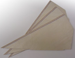
On the right you can see the plywood fin cores. The only thing done so far is the leading edge (long edge) has been beveled using my fin beveling jig.
The fins are 3/16" plywood and were flat and cleanly cut. However, I just couldn't let them remain plain wood so I decided to reinforce them. One layer of carbon fiber makes them harder, stiffer and easier to finish.
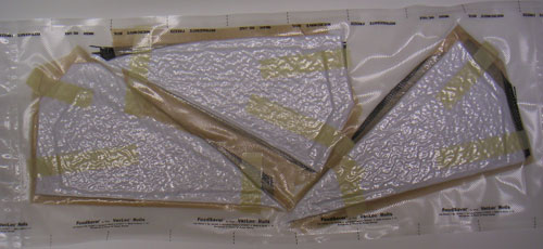
Above you can see the three fins in the FoodSaver® vacuum bag with the reinforcement applied to both sides. Small fins are nice and easy to work with.
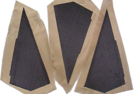
After a couple of hours in the bag, out come the fins and the excess reinforcement is trimmed off with an X-acto® knife (while the epoxy is still at the "leather" stage and cut be cut cleanly). They always look so nice in black!
Original Kit Info
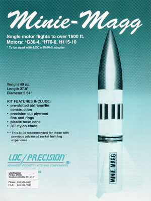 |
Single motor flights to over 1600 ft.
Motors: *G80-4, *H70-6, H115-10 * To be used with LOC's MMA-2 adapter
Weight 40 oz.
KIT FEATURES INCLUDE:
*** This kit is recommended for those with previous advanced rocket building experience. |